Analogue Electronics 1 2017 (PDF)
File information
Title: Microsoft PowerPoint - Analogue Electronics_1_2017
Author: pe0009
This PDF 1.5 document has been generated by / Bullzip PDF Printer / www.bullzip.com / Freeware Edition, and has been sent on pdf-archive.com on 12/01/2018 at 15:15, from IP address 131.227.x.x.
The current document download page has been viewed 558 times.
File size: 1 MB (98 pages).
Privacy: public file


File preview
12/09/2017
Electronics 1
• This course is in two parts
• A. Circuit theory – Keith Ryden
– This part will cover the fundamentals of electronic
circuits and their analysis
• B. Analogue electronics – Philip Evans
– This part will cover practical analogue electronics
and their design and analysis
1
Analogue electronics: Course Syllabus
• Fundamentals
Resistive networks, voltage and current sources, Thevenin and Norton
equivalent circuits, current and voltage division, input resistance, output
resistance, coupling and decoupling capacitors, maximum power transfer, RMS
and power dissipation, current limiting and over voltage protection
• Components and active devices
Components vs elements and circuit modelling, real and ideal elements.
Introduction to sensors and actuators, self-generating vs modulating type
sensors, simple circuit interfacing
• Diodes and diode circuits
Diode characteristics and equations, ideal vs real. Signal conditioning clamping
and clipping, rectification and peak detection, photodiodes, LEDs, Zener
diodes, voltage stabilisation, voltage reference, power supplies
2
1
12/09/2017
Level 1 Module
Electronics 1
Analogue Electronics
Phil Evans
Lecture 1 – Resistive networks
3
Fundamental properties
• Begin with a look at the fundamental
properties of circuits
– Resistance
– Current
– Voltage
4
2
12/09/2017
Resistance
• Resistance is the property of a circuit that opposes the flow of
current in response to a voltage.
• Measured in Ohms = volts/ampere
– i.e. a voltage is required to generate current flow
• Ohms law describes this relationship:
V = IR I = V / R R = V / I
• This is a linear relationship where R is (approximately)
constant passing through the origin
I
V
Slope of the line ∂I/ ∂V = 1/R = conductance (measured in Siemans = Ω-1)
5
Current
• Absolute quantity
– Measurement of number of electrons passing a point per
second
– e = 1.6 x 10⁻¹⁹ C
– 1A ≈ 0.6 x 10¹⁹ electrons/second
– 1pA ≈ 6 million electrons/second
6
3
12/09/2017
Voltage
• Relative measurement
– Always need a reference point → potential difference
between 2 points
– Ohm’s law relates resistance, current and the voltage drop
across the resistor → V1 – V2 = IR
•
•
•
•
Power at any moment = V(t) x i(t) 2
Power dissipated in a resistor = V (t ) = i 2 (t ) R
R
For an AC supply V(t) = Vmax sin (ωt)
Instantaneous current = V (t )
V sin(ωt )
R
= I (t ) =
max
R
= I max sin(ωt )
Note that current and voltage are in phase
7
Resistors
• Two terminal devices with a specified value of resistance
• Values measured in ohms, kΩ, MΩ etc.
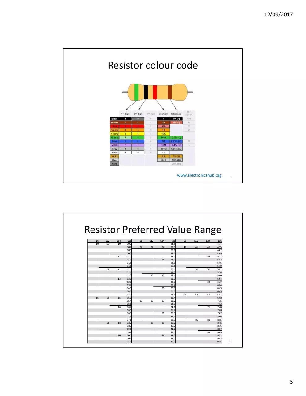
• Available in preferred values in ranges E6, E12, E24, E48, E96
– Divides ranges into 6,12,24,48,96 values
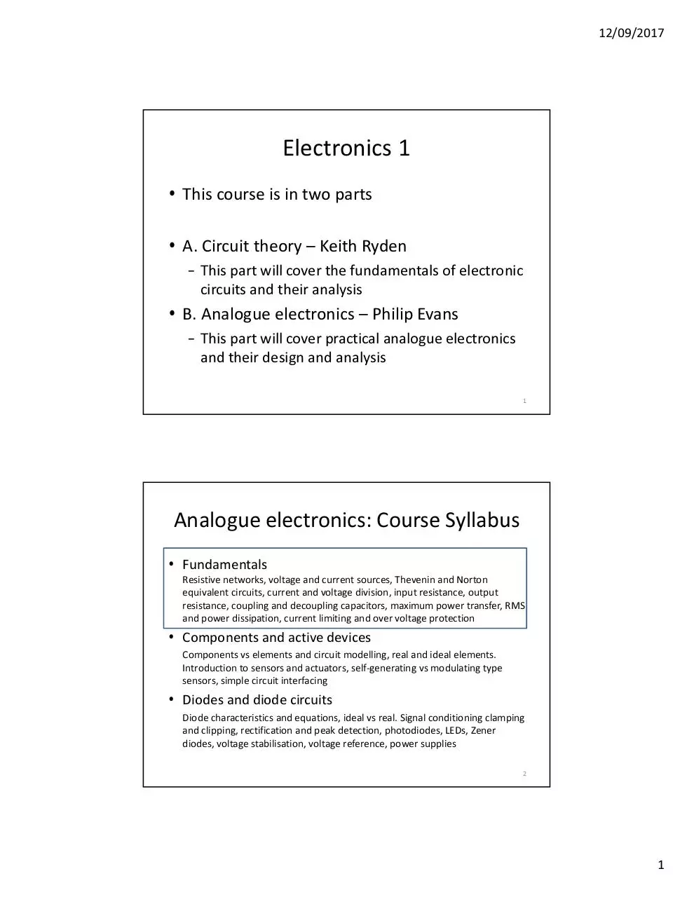
• Colour codes
–
–
–
–
1st band – 1st digit
2nd band – 2nd digit
3rd band – multiplier
4th band – tolerance
Must also specify resistor power handling capacity
8
4
12/09/2017
Resistor colour code
www.electronicshub.org
9
Resistor Preferred Value Range
E6
10
E12
10
E24
10
11
12
12
13
15
15
15
16
18
18
20
E96
10.0
10.2
10.5
10.7
11.0
11.3
11.5
11.8
12.1
12.4
12.7
13.0
13.3
13.7
14.0
14.3
14.7
15.0
15.4
15.8
16.2
16.5
16.9
17.4
17.8
18.2
18.7
19.1
19.6
20.0
20.5
21.0
E6
E12
E24
22
22
22
24
27
27
30
33
33
33
36
39
39
43
E96
21.5
22.1
22.6
23.2
23.7
24.3
24.9
25.5
26.1
26.7
27.4
28.0
28.7
29.4
30.1
30.9
31.6
32.4
33.2
34.0
34.8
35.7
36.5
37.4
38.3
39.2
40.2
41.2
42.2
43.2
44.2
45.3
E6
E12
E24
47
47
47
51
56
56
62
68
68
68
75
82
82
91
E96
46.4
47.5
48.7
49.9
51.1
52.3
53.6
54.9
56.2
57.6
59.0
60.4
61.9
63.4
64.9
66.5
68.1
69.8
71.5
73.2
75.0
76.8
78.7
80.6
82.5
84.5
86.6
88.7
90.9
93.1
95.3
97.6
10
5
12/09/2017
Web Resources
• Various web resources to practice resistor identification:
– http://www.funtrivia.com/playquiz/quiz2664721e821c8.html
– https://en.wikipedia.org/wiki/List_of_electronic_color_code_mnemon
ics - Bad Booze Rots Our Young Guts But Vodka Goes Well
11
Temperature stability
• Typically 0.019%/°C – 0.05%/°C
• Time stability 50 ppm/month (0.005%)/month
• Voltage limits also apply e.g. 0.25W – 350Vmax typically
12
6
12/09/2017
Combinations of Resistors:
Resistive networks
• In series
– RT = R1 + R2 + R3
– Beware of tolerances – 100 kΩ (5%) + 1 kΩ (5%) ≠ 101 kΩ
Due to the tolerance
• In parallel
– 2 resistors
– 3 resistors
1
1
1
R1R 2
=
+
⇒ RT =
RT
R1
R2
R1 + R 2
RT =
R1R2 R3
R1 R2 + R2 R3 + R1R3
1 power less in denominator
13
Combinations of Resistors
• Short cuts for mental arithmetic
5kΩ ≡ 2 x 10k in parallel or 10k//10k=5k
So 10k//5k ≡ 3 x 10k = 10k/3 = 3k33
R1//R2: if R1 = nR2 then RT = R1/(n+1)
Or if mR1 = nR2 = R then RT = R/(n+m)
e.g. 22k/33k ≡ (3x66k)//(2x66k)
(m)
(n)
= 5x666k in parallel = 66k/(3+2) = 66k/5 = 13k2
14
7
12/09/2017
Class examples
Find the resistance between A and B
A
5Ω
30 Ω
30 Ω
B
15
Class examples
Find the resistance between A and B
A
30 Ω
30 Ω
30 Ω
50 Ω
B
16
8
12/09/2017
Class examples
Find the resistance between A and B
A
2 kΩ
4.5 kΩ
1.4 kΩ
2.7 kΩ
B
17
Class examples
Find the resistance between A and B
A
320 kΩ
200 kΩ
160 kΩ
150 kΩ
B
18
9
Download Analogue Electronics 1 2017
Analogue Electronics_1_2017.pdf (PDF, 1 MB)
Download PDF
Share this file on social networks
Link to this page
Permanent link
Use the permanent link to the download page to share your document on Facebook, Twitter, LinkedIn, or directly with a contact by e-Mail, Messenger, Whatsapp, Line..
Short link
Use the short link to share your document on Twitter or by text message (SMS)
HTML Code
Copy the following HTML code to share your document on a Website or Blog
QR Code to this page

This file has been shared publicly by a user of PDF Archive.
Document ID: 0000720297.