FLOW45 Installation manual (PDF)
File information
Title: FLOW45
Author: Marcel MaceÄek
This PDF 1.5 document has been generated by Microsoft® Word 2013, and has been sent on pdf-archive.com on 13/02/2018 at 21:53, from IP address 81.30.x.x.
The current document download page has been viewed 353 times.
File size: 2.39 MB (28 pages).
Privacy: public file


File preview
FLOW 45
Installation and technical conditions
Date of issue 11/05/2017
Manual FLOW 45
Page 1 (total 28)
COMAC CAL s.r.o.
Contents:
Description of device ............................................................................................................................. 3
Scope of delivery ............................................................................................................................... 3
Storage conditions ................................................................................................................................. 4
Warranty ................................................................................................................................................ 4
Installation in pipeline .......................................................................................................................... 5
Important information for selection of location ................................................................................. 5
Sources of disturbances ...................................................................................................................... 5
Installation examples.......................................................................................................................... 6
Actual installation in pipeline ............................................................................................................ 7
Installation check ............................................................................................................................. 13
Wiring .................................................................................................................................................. 13
Important information ...................................................................................................................... 13
Installation of the meter's detached evaluation unit ......................................................................... 14
Meter wiring ..................................................................................................................................... 15
Wiring check .................................................................................................................................... 16
Putting into operation ......................................................................................................................... 16
Technical data ..................................................................................................................................... 20
Factory settings ................................................................................................................................... 21
Basic sensor sizes ................................................................................................................................ 22
Nomogram for quick proposal of the measured place ....................................................................... 26
Reduction in DN pipe ...................................................................................................................... 26
Faults and their symptoms during measurement.............................................................................. 27
Flow sensor cleaning .......................................................................................................................... 27
Servicing .............................................................................................................................................. 27
Form for shipment of the meter back to COMAC CAL s.r.o. ........................................................... 28
Manual FLOW 45
Page 2 (total 28)
COMAC CAL s.r.o.
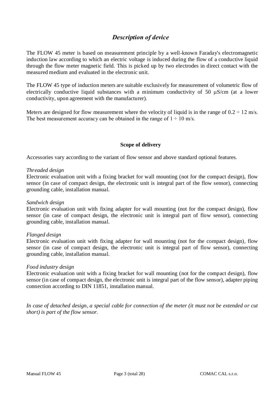
Description of device
The FLOW 45 meter is based on measurement principle by a well-known Faraday's electromagnetic
induction law according to which an electric voltage is induced during the flow of a conductive liquid
through the flow meter magnetic field. This is picked up by two electrodes in direct contact with the
measured medium and evaluated in the electronic unit.
The FLOW 45 type of induction meters are suitable exclusively for measurement of volumetric flow of
electrically conductive liquid substances with a minimum conductivity of 50 S/cm (at a lower
conductivity, upon agreement with the manufacturer).
Meters are designed for flow measurement where the velocity of liquid is in the range of 0.2 ÷ 12 m/s.
The best measurement accuracy can be obtained in the range of 1 ÷ 10 m/s.
Scope of delivery
Accessories vary according to the variant of flow sensor and above standard optional features.
Threaded design
Electronic evaluation unit with a fixing bracket for wall mounting (not for the compact design), flow
sensor (in case of compact design, the electronic unit is integral part of the flow sensor), connecting
grounding cable, installation manual.
Sandwich design
Electronic evaluation unit with fixing adapter for wall mounting (not for the compact design), flow
sensor (in case of compact design, the electronic unit is integral part of flow sensor), connecting
grounding cable, installation manual.
Flanged design
Electronic evaluation unit with fixing adapter for wall mounting (not for the compact design), flow
sensor (in case of compact design, the electronic unit is integral part of flow sensor), connecting
grounding cable, installation manual.
Food industry design
Electronic evaluation unit with a fixing bracket for wall mounting (not for the compact design), flow
sensor (in case of compact design, the electronic unit is integral part of the flow sensor), adapter piping
connection according to DIN 11851, installation manual.
In case of detached design, a special cable for connection of the meter (it must not be extended or cut
short) is part of the flow sensor.
Manual FLOW 45
Page 3 (total 28)
COMAC CAL s.r.o.
Storage conditions
The temperature during transportation and storage of the meter must be within the range of -10 °C to 50
°C.
Wooden boards installed on the flanges in the factory are used for protection of lining on the flanges
during storage and transportation (for PTFE lining). Remove these protective boards just before
installing in the pipeline!!!
Do not lift the flanged meters by the transducer head or by the connecting box of the detached design
during transportation! Use slings and place them round both process connections for transportation of
meters up to DN125 (chains may damage the meter head)! Use only the metallic lugs on the flange for
transportation, lifting and installation of the sensor in piping in case of DN150 and bigger!!!
Warranty
Unprofessional installation or using the induction meters (devices) may result in a loss of warranty as
well as failure to comply with installation or operating conditions according to this manual.
In case of returning the meters for inspection or repair to the COMAC CAL s.r.o. factory, enclose please
the completed form, see the last page of this manual. Without having one, we will not be able to handle
your requirement for modification or possibly repair your meter correctly and promptly.
Manual FLOW 45
Page 4 (total 28)
COMAC CAL s.r.o.
Installation in pipeline
Important information for selection of location
!!! In case of detached design, the cable must not be extended or cut short !!!
Outdoor conditions
It is necessary to ensure that the flow sensor is not exposed to weather effects and that the measured
medium cannot freeze in the flow sensor as it would damage the measuring tube.
In case of outdoor location of the electronic evaluation unit, the manufacturer recommends using a
protective box or a roof to avoid direct solar exposure so that the evaluation electronics cannot get
overheated.
Sources of disturbances
The following items rank among the most frequent sources of disturbances to the steady flow of liquid:
Abrupt changes in pipe cross-section if not performed as a cone with an angle of 7° (where
is the angle made by bevelled walls of the pipe reduction).
Incorrectly centred sealing, low ID sealing or sealing made of soft elastic materials which are
pushed out into the interior pipe cross-section after flanges are tightened.
Anything interfering in the flow of liquid, for example thermowells, branch pipes, T-pieces, bends,
elbows, slide valves, cocks, flap valves, shut-off valves, control valves, butterfly valves and check
valves. Pipe outlets from tanks, heat exchangers and filters.
No intensive magnetic fields in the proximity of the induction flow sensor (detector) must be
present.
No sources of disturbances affecting the steady flow must be present in the straight pipeline sections.
They must be located in the piping after the flow sensor or at the farthest distance before it. Sources of
disturbances may substantially reduce the measuring range and accuracy of the flow meters.
Vibration
We recommend supporting the connecting pipes on both sides of the meter for partial elimination of
vibrations. Levels and range of vibrations must be under 2.2g in the frequency range of 20 ÷ 50 Hz
according to IEC 068-2-34. If the pipeline is exposed to excessive vibrations (e.g. from pumps), using
compact meters is not recommended.
Actual location
The flow sensor (detector) must not be at the top position of the pipe which may be airlocked, or in
declining or even in horizontal pipelines with open ends in which air may penetrate. Impurities may
accumulate during long-term measurement of very low flow rates Q < 0.1 m/sec. There must be a
sufficient pressure in the place of flow sensor installation so that the expulsion of gas or vapour bubbles
from the liquid is avoided. Little bubbles that always occur in liquids may accumulate at any of the
electrodes and this may result in incorrect operation of the meter. Gas bubbles are expelled also at an
abrupt pressure drop. Therefore, butterfly valves and similar elements should be located after the flow
sensor. For the same reason, the flow sensor should not be placed at the suction side of the pump. To
prevent the bubbles from accumulation at a low flow in the flow sensor, it is suitable, e.g. that the pipe
is slightly ascending or that the flow sensor is located in the vertical section of the pipeline.
Manual FLOW 45
Page 5 (total 28)
COMAC CAL s.r.o.
In the case that the sensor is equipped with an empty pipe testing electrode (3rd or 4th electrode in the
upper part of the measuring tube profile), there is no risk of erroneous readout of quantity of liquid
passing through the meter due to aeration of measuring electrodes.
The function of empty tube detection in horizontal mounting position
operates correctly only if the evaluation unit is oriented upwards (see Fig.
on right). Alternatively, it is not possible to ensure that the activation of
empty tube detection in case of partly filled or empty pipes will take place.
Due to the principle, it is necessary that the maximum
conductivity of medium is 6000 µS for ensuring the
functional evaluation of empty tube. Beyond this limit, errors
may occur in empty tube test, and in this case, it is necessary
to deactivate the empty tube test. If the conductivity of
medium is beyond the permissible range, the meter may,
despite the flooded system, register empty pipeline and the
measurement will not start.
In case of any intervention into the measuring circuit must be accessed like a pipe is fulfilled of
medium, and regardless of the displayed information “empty pipe test” on the display meter !!!
Installation examples
Trouble-free and exact operation of the meter is dependent on its correct location in the system. The
most frequent methods of the placement are shown in the following figures:
Recommended installation locations
Downtake pipe
Bubbles are accumulated in the
pipeline; erroneous measurement
Install an air bleed valve
after the sensor
Correct
location
Pipeline is
empty;
erroneous
measurement
Horizontally laid pipeline
Long pipeline
Place the sensor in a slightly
ascending pipeline
Manual FLOW 45
Install controls and shut-off
valves always after the sensor
Page 6 (total 28)
COMAC CAL s.r.o.
Free inlet or outlet
Pumps
The flow meter must not be installed
in the suction side of the pump
Built in the U-shaped pipeline
The flow of liquid flow in the flow sensor should be steady and free of whirling. For this reason,
straight sections of pipeline with the same ID as that of the flow meter before and after the flow sensor
(with permissible deviation of +5%). Recommended minimum length of straight sections is 5d before
the flow sensor and 3d after the flow sensor where d is the inside diameter of the meter in millimetres.
The same principles apply before and after the flow sensor in case of bi-directional flow measurement.
Recommendations
In case of whirled up flow, extend the calming sections of pipeline or integrate a flow conditioner.
When blending a mixture of substances, it is necessary to install the flow meter either before the
point of blending or at a sufficient distance after it (30d min. where d is the inside diameter of
the meter in millimetres), otherwise it will result in instability of indication.
When plastic pipeline is used or in case of metallic pipes with internal non-conductive layer,
earthing rings are needed.
Do not install the sensor at the suction side of the pumps; this will eliminate the risk of vacuum
and possible damage to the measuring tube lining.
Pumps, bends and elbows found closely in succession in various levels should be at a distance
of 20d at least before the flow sensor. In case of a separate elbow or bend, the placement 10d
before the meter is recommended.
When piston pumps, diaphragm pumps, and flexible tube pumps are used, it is necessary to install
a pulse damper in the system.
In order to provide the highest accuracy, it is important to ensure permanent flooding for the
sensor (for example, by installation of the sensor in the U-shaped pipeline) even if the sensor is
equipped with empty tube test. This will serve as an additional safety measure for detection of
non-flooded tube.
The responsibility for suitability and adequacy of application of induction flow meters is borne by the
designer or possibly the user himself.
Actual installation in pipeline
When welding both counter-flanges to the pipelines, it is
necessary to maintain their alignment so that levelness of bearing
surfaces of the flanges onto the front faces of the detector is
ensured (at the same time, this must not be achieved by unequal
tightening of the bolts as there is a risk of leakage due to thermal
loading in the future or the measuring tube may break during such
tightening). The difference of LMAX and LMIN distances of the
sealing surfaces of the flanges before the flow sensor is installed
must not be greater than 0.5 mm.
Manual FLOW 45
Page 7 (total 28)
COMAC CAL s.r.o.
The opposition of the holes in the counter-flanges for the bolts should be ensured in the same manner
and a sufficient room behind the flanges should be available for the bolts and nuts so that the actual
installation of the sensor in pipeline and its attachment with the bolts is made possible.
The manufacturer recommends using an intermediate piece during welding. It is absolutely excluded to
use the flow sensor as an intermediate piece due to thermal damage. The welding current must not run
through the flow sensor during electrical welding. The installation of the flow sensor is carried out after
welding, coating, building and similar works are completed.
The actual installation is performed by the fixation between the counter-flanges that are welded to the
calming pipeline (5×d before and 3×d in the direction of flow) whereas the liquid must run through the
flow sensor in the direction indicated by the arrow on the sensor name plate.
During installation, do not lift the meter by the evaluation unit housing (in case of detached design, by
the sensor terminal box), possibly under the meter's metallic housing but always use slings round the
process connection or use the lifting lugs on the flanges.
Installation position
The inductive flow sensor is installed in arbitrary position in vertical piping. In case of horizontal piping,
it is necessary to make sure that the sensor is installed with its measuring electrodes in horizontal
position. In case of the earthing electrode design, possibly with testing for empty pipeline, then the
installation is always performed with the earthing reference electrode facing down (with the sensor
terminal box, eventually with the evaluation unit facing upwards). Then the earthing reference electrode
is in the bottom position and the empty tube sensing electrode is in the top position of the flow sensor.
Every time when the empty tube testing electrode is not covered
with a liquid for 5sec at least, the flow meter will display the
"Empty tube" status, and if it is necessary, it sends out an error
message and stops taking measurement. The measurement
accuracy is maintained in this way. Once the electrode is
covered with the liquid again, the error message disappears and
the flow meter starts taking measurement again.
Manual FLOW 45
Page 8 (total 28)
COMAC CAL s.r.o.
Installation in piping and placement of measuring electrodes in flow sensor
Version with earthed electrode and empty piping test electrode
During installation, beware of:
- dropping the meter onto the ground and damaging the measuring tube or electronics
- contamination of the electrodes (do not touch the electrodes, otherwise they get contaminated)
- when additional sealing is used, avoid its interference in the flow profile of the detector
between the flanges and the pipeline, otherwise the flow measurement error may be increased
Tightening torques
It is absolutely necessary to tighten the bolts and nuts equally by alternating sides and in the order shown
in figure applying the maximum torque according to the table.
If the bolts are tightened too much during the installation of pipework components, deformation of the
sealing surface may occur. In consequence, the torque values indicated in the table are used as a
guidance for tightening the screws and bolts.
Manual FLOW 45
Page 9 (total 28)
COMAC CAL s.r.o.
Download FLOW45 Installation manual
FLOW45 Installation manual.pdf (PDF, 2.39 MB)
Download PDF
Share this file on social networks
Link to this page
Permanent link
Use the permanent link to the download page to share your document on Facebook, Twitter, LinkedIn, or directly with a contact by e-Mail, Messenger, Whatsapp, Line..
Short link
Use the short link to share your document on Twitter or by text message (SMS)
HTML Code
Copy the following HTML code to share your document on a Website or Blog
QR Code to this page

This file has been shared publicly by a user of PDF Archive.
Document ID: 0000733938.