CELL PHONE CHARGER (PDF)
File information
Author: Windows User
This PDF 1.5 document has been generated by Microsoft® Word 2016, and has been sent on pdf-archive.com on 17/03/2018 at 10:39, from IP address 117.247.x.x.
The current document download page has been viewed 361 times.
File size: 696.51 KB (18 pages).
Privacy: public file

File preview
A
PROJECT REPORT ON
“CELL PHONE CHARGER”
SUBMITTED TO: ROORKEE COLLEGE OF ENGINEERING
SUBMITTED BY: SANDEEP MAURYA
DEPARTMENT OF
ELECTRONICS AND COMMUNICATION ENGINEERING
ROORKEE COLLEGE OF ENGINEERING,
ROORKEE, UTTRAKHAND
PROJECT REPORT ON
“CELL PHONE CHARGER”
SUBMITTED BY: SANDEEP MAURYA
GUIDED BY: I.P. CHANDRA
MRS. NISHA DHIMAN
MISS. PRIYANKA SINGH RANA
DEPERTMENT OF ELECTRONICS AND COMMUNICATION
ROORKEE COLLAGE OF ENGINEERING,
ROORKEE, UTTRAKHAND
ACKNOWLEDGEMENT
I place on record and warmly acknowledge the continuous
encouragement, Invaluable supervision, timely suggestions and inspired
guidance offered by our guide I.P. CHANDRA, MRS.NISHA
DHIMAN, MISS. PRIYANKA SINGH RANA, Professor,
Department of Electronics and Communication, ROORKEE
COLLAGE OF ENGINEERING, ROORKEE UTTRAKHAND, in
bringing this report to a successful completion. I have taken efforts in
this project. However , it would not have been possible without the kind
support.
I am grateful to Dr. SANGRAM SINGH BANA, Head of
the Department of Electronics And Communication, for permitting me
to make use of the facilities available in the department to carry out the
project successfully. Last but not the least I express my sincere thanks to
all of my friends who have patiently extended all sorts of help for
accomplishing this undertaking.
Finally I extend our gratefulness to S.K. GUPTA
(CHAIRMAN) and all those who are directly or indirectly involved in
the successful completion of this project work.
.
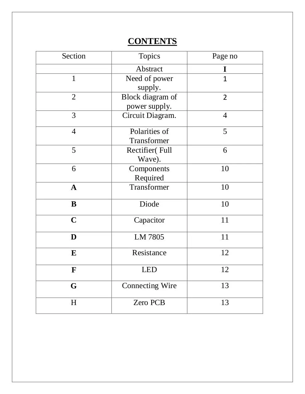
CONTENTS
Section
Topics
Page no
Abstract
Need of power
supply.
Block diagram of
power supply.
Circuit Diagram.
I
1
5
A
Polarities of
Transformer
Rectifier( Full
Wave).
Components
Required
Transformer
B
Diode
10
C
Capacitor
11
D
LM 7805
11
E
Resistance
12
F
LED
12
G
Connecting Wire
13
H
Zero PCB
13
1
2
3
4
5
6
2
4
6
10
10
ABSTRACT
Every electronics circuit such as amplifiers, battery chargers,
needs a DC power source for its operation. The DC voltage has to
obtained from the AC supply. For this the AC supply voltage has to be
reduced (step down) first using a step down transformer and then
converted to DC by using a rectifier.
A step down transformer is used to reduce the Ac mains voltage to
adequately small value. The turns ratio of the transformer is adjusted to
obtain a stepper down Ac voltage.
This voltage is converted into a pulsating Dc voltage by the
rectifier. The type of rectifier used are half wave rectifier, full wave
rectifier or bridge rectifier.
This pulsating Dc voltage at the rectifier output is converted into
a ripple free study Dc voltage by the filter circuit. The ripple or the Ac
part in the voltage in the voltage is minimized by the filter.
The filtered Dc voltage is then applied to a voltage regulator
which tries to keep the Dc output voltage constant even if the supply
voltage or load fluctuations takes place.
I
TOPIC:Cell Phone Charger
NEED OF POWER SUPPLY:Every electronics circuit such as amplifiers, battery chargers, needs a
DC power source for its operation. The DC voltage has to obtained from
the AC supply. For this the AC supply voltage has to be reduced (step
down) first using a step down transformer and then converted to DC by
using a rectifier. A power supply is an electrical device that supplies
electric power to an electrical load. The primary function of a power
supply is to convert electric current from a source to the correct voltage,
current, and frequency to power the load. As a result, power supplies are
sometimes referred to as electric power converters.
1
BLOCK DIAGRAM OF A REGULATED POWER
SUPPLY:-
OPERATION:The basic building block of a regulated DC power supply are:
A step down transformer
A rectifier
Filter
Voltage regulator
2
A step down transformer is used to reduce the Ac mains voltage to
adequately small value. The turns ratio of the transformer is adjusted to
obtain a stepper down Ac voltage.
This voltage is converted into a pulsating Dc voltage by the rectifier.
The type of rectifier used are half wave rectifier , full wave rectifier or
bridge rectifier.
This pulsating Dc voltage at the rectifier output is converted into a
ripple free stedy Dc voltage by the filter circuit. The ripple or the Ac part
in the voltage in the voltage is minimized by the filter.
The filtered Dc voltage is then applied to a voltage regulator which
tries to keep the Dc output voltage constant even if the supply voltage or
load fluctuations takes place.
3
CIRCUIT DIAGRAM:-
4
Download CELL PHONE CHARGER
CELL PHONE CHARGER.pdf (PDF, 696.51 KB)
Download PDF
Share this file on social networks
Link to this page
Permanent link
Use the permanent link to the download page to share your document on Facebook, Twitter, LinkedIn, or directly with a contact by e-Mail, Messenger, Whatsapp, Line..
Short link
Use the short link to share your document on Twitter or by text message (SMS)
HTML Code
Copy the following HTML code to share your document on a Website or Blog
QR Code to this page

This file has been shared publicly by a user of PDF Archive.
Document ID: 0000746127.