JL 4 Door Install Instructions V2.1 (PDF)
File information
Author: Casey
This PDF 1.7 document has been generated by Microsoft® Publisher 2016, and has been sent on pdf-archive.com on 27/04/2018 at 23:08, from IP address 73.65.x.x.
The current document download page has been viewed 367 times.
File size: 8.91 MB (10 pages).
Privacy: public file


File preview
INSTALLATION MANUAL
STEP SLIDER
BD-SS-200-JL4
Made in the USA
Description
Quantity
Electric Step Slider (Pair)
2
Bump stop plate with VHB backing
2
Wiring harness (2 piece)
1
Double sided adhesive squares
12
Door sensor
4
Magnets
4
Alcohol wipes
4
Rocker cutoff switch
1
Anti-seize packet
1
Circuit board
1
5/16” - 18 nylock nut
8
5/16” stainless steel washer
8
1/4” - 20 nylock nut
4
1/4” - 20 stainless steel washer
4
1/4” - 20 X 1” grade 8 hex head bolt
24
1/4” SAE yellow zinc washer
24
Front bracket (short style)
2
Middle bracket (long style)
2
Rear brackets (drop style)
2
Tools Required
10 mm socket
7/16” socket
18 mm socket
1/2” socket
Breaker bar
Wrench with 3-4”
extension
**Optional for quicker install
Torx Gun with adapters
Heavy Duty Torx Gun
with 1/2” driver
7/16” Box end ratchet- 1/2” Box end ratcheting
ing wrench
wrench
ROCKSLIDEENGINEERING.COM - NEED ASSISTANCE? 435.752.4580 - PAGE 1
REVISED 4/27/2018
ROCKSLIDEENGINEERING.COM - NEED ASSISTANCE? 435.752.4580 - PAGE 2
REVISED 4/27/2018
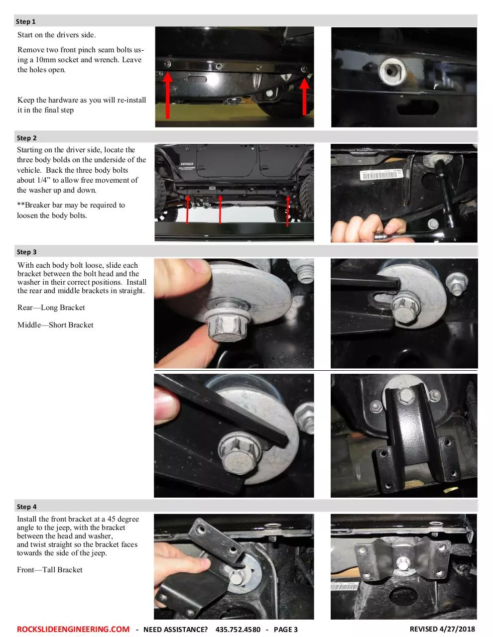
Step 1
Start on the drivers side.
Remove two front pinch seam bolts using a 10mm socket and wrench. Leave
the holes open.
Keep the hardware as you will re-install
it in the final step
Step 2
Starting on the driver side, locate the
three body bolds on the underside of the
vehicle. Back the three body bolts
about 1/4” to allow free movement of
the washer up and down.
**Breaker bar may be required to
loosen the body bolts.
Step 3
With each body bolt loose, slide each
bracket between the bolt head and the
washer in their correct positions. Install
the rear and middle brackets in straight.
Rear—Long Bracket
Middle—Short Bracket
Step 4
Install the front bracket at a 45 degree
angle to the jeep, with the bracket
between the head and washer,
and twist straight so the bracket faces
towards the side of the jeep.
Front—Tall Bracket
ROCKSLIDEENGINEERING.COM - NEED ASSISTANCE? 435.752.4580 - PAGE 3
REVISED 4/27/2018
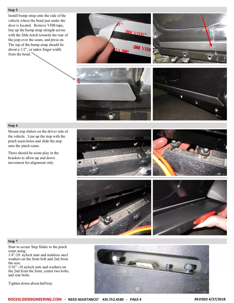
Step 5
Install bump strap onto the side of the
vehicle where the bend just under the
door is located. Remove VHB tape,
line up the bump strap straight across
with the little notch towards the rear of
the jeep over the seam, and press on.
The top of the bump strap should be
about a 1/2”, or index finger width
from the bend.
Step 6
Mount step sliders on the driver side of
the vehicle. Line up the step with the
pinch seam holes and slide the step
onto the pinch seam.
There should be some play in the
brackets to allow up and down
movement for alignment only.
Step 7
Start to secure Step Slider to the pinch
seam using:
1/4”-20 nylock nuts and stainless steel
washers on the front bolt and 2nd from
the rear.
5/16” -18 nylock nuts and washers on
the 2nd from the front, center two bolts,
and rear bolts.
Tighten down about halfway.
ROCKSLIDEENGINEERING.COM - NEED ASSISTANCE? 435.752.4580 - PAGE 4
REVISED 4/27/2018
Step 8
Install 12 5/16” - 18 x 1” with a hex
head bolts with yellow SAE washers
into the bracket through the slots on
the underside of the step slider.
Install bolts halfway.
Step 9
Once all bolts and nuts have been started, tighten down pinch seam nuts:
Use a 1/2” socket and wrench with a
3-4” extension for the 5/16” - 18 nuts.
Use a 7/16” socket and wrench with a
3-4” extension 1/4 - 20 nuts.
Torque 5/16” nuts to 18 ft. lbs.
Torque 1/4” nuts to 9 ft. lbs.
Step 10
Tighten down 5/16” hex hex using a
1/2” socket and wrench.
Torque to 18 ft. lbs.
**For a quicker install, use a torx gun
with an adapter for a 1/2” socket.
Step 11
Tighten down body bolts last.
Torque to 80 ft. lbs.
Repeat steps 1-11 on
the passenger side
ROCKSLIDEENGINEERING.COM - NEED ASSISTANCE? 435.752.4580 - PAGE 5
REVISED 4/27/2018
Step 12
Remove floor mats from the jeep.
Loosen front kick panel.
Remove center panel to allow access
for wires.
Step 13
Remove fuse from harness.
Attach RED—POSITIVE and the
BLACK—NEGATIVE.
Route the harness across the engine
bay and through the firewall.
Zip tie into place.
ROCKSLIDEENGINEERING.COM - NEED ASSISTANCE? 435.752.4580 - PAGE 6
REVISED 4/27/2018
Step 14
Unravel the large harness in the rear
seat and route the connectors to the
front of the vehicle under the removed
panels.
Step 15
Remove floor plug.
Run motor connector through the open
hole.
**If installing optional light kit, run
light connector down through the hole.
Run circuit board plug and passenger
side connectors under the carpet to the
passenger side of the vehicle.
Remove plug on the passenger side of
the vehicle.
Route motor wire through the hole.
**If installing optional light kit, run
light connector down through the hole.
Step 16
Refer to diagram below and page 2
for sensor location and wire color.
Plug sensors into harness. Route
sensor to door jam. Install on each
door under the latch as shown.
ROCKSLIDEENGINEERING.COM - NEED ASSISTANCE? 435.752.4580 - PAGE 7
REVISED 4/27/2018
Step 17
Install magnets onto the door
Step 18
Locate a spot to install the power
switch. We recommend the kick panel
or lower left dash panel.
Use a 3/4” bit to drill a hole to install
the cutoff rocker switch. If the hole is
too tight, increase hole size until the
switch installs easily.
Plug the blue female wire into the
silver male ends and the red female
wire into the bronze male end.
Install rocker switch into dash or chosen spot.
Ensure to ground black wire onto the
jeep body.
Step 19
Once all sensors are installed and the
wiring has been run, plug the small
wiring harness into the large harness.
Plug in circuit board to the large harness and secure it under
Reinstall fuse into harness
Step 19
Re-install the panel bolts removed in
step 1.
ROCKSLIDEENGINEERING.COM - NEED ASSISTANCE? 435.752.4580 - PAGE 8
REVISED 4/27/2018
TROUBLESHOOTING YOUR STEP SLIDERS:
I just installed my steps and they are
not coming down when I open the door.
Double check the connections. Check the fuse to make sure it is plugged in. Is the on / off
switch getting power? Is the circuit board plugged in? Are the door sensors plugged in?
My switch is getting power, but
the light stays on in both positions.
The light is only supposed to be on when the system is turned on. If it is lit in both positions
simply switch the red wires on the back. Will this kill my battery with the light constantly lit?
This will not kill your battery unless you leave it lit for a month with no use.
Everything is plugged in and the switch is Two things may be causing this issue:
turning on and off, but the steps still won't
Check the motor first. Simply unplug it from the wiring harness and apply external 12V power
deploy.
to the leads. One position will make them deploy. Switch the leads again to make them retract.
If this works, plug the motor back into the harness. We test each and every motor that leaves
our factory by hand along with assembling your step slider by hand. These may fail, but it is
extremely rare after we send them after having tested them. If you test the motor and all you
hear is a clicking sound but nothing happens, there is likely internal damage.
Check the sensors. Unplug both of them from the wiring harness, and plug one back in. Manually test your sensors by putting a magnet really close (but not touching) to the sensor. Does it
make the step retract? When the magnet is away, the step should deploy. If the steps deploy
right after installation, more than likely your magnets just need to be aligned. Do this one by
one with each sensor by the method above. Install one sensor, test, align the magnet on the
door, test, and then mark the position of the magnet so if for some reason they do move out of
place you can easily realign them. The sensors should have a label with MP###802 or
MP###902.
I tested the motor, and it works. I checked In rare circumstances, the circuit board that runs the system may be faulty.
the sensors individually, and the system
still won't work. The steps don't deploy
Call our support team for a warranty help at 435-752-4580
unless I do it manually with 12V power.
I opened my door a bunch of times and
the system just shut off. What happened?
Our systems have built-in protection against quick cycling like this to prevent damage.
Simply turn your on / off switch to off, wait 5 seconds, and then turn it on again.
This will reset the system and allow it to work normally again.
Everything is working now. But I want to
take my doors off and have the steps still
work.
We sell a door delete kit you can replace those sensors with. Part# SL-DD-100
comes with everything you need for two doors. If you want to install a delete kit
on the rear doors as well, you will need to purchase two kits.
The steps deployed and won’t retract.
What is going on?
Chances are your magnets are misaligned. To diagnose which door needs to be adjusted, unplug the rear sensors with the front doors closed. If your steps come up, then it was the rear
doors that need to be aligned with your magnet. If the step stays down, the front door needs to
be aligned. Open your door, shift the magnet in a direction, and shut it again. Repeat until the
step comes up when the door is shut. Mark the magnet placement on the front door. Plug the
rear door sensor in, shut the rear door and front door, and see if it comes up. If not, the rear
door is misaligned (Since we just aligned the front door we know it’s the rear door now). Repeat the previous process of opening your door, shifting your magnet, and shutting your door
until the step comes up. It may take a few tries.
I was off-roading, left my system on, some- We can replace these parts for you at cost. You will have to remove the step off your vehicle
one left the door ajar and I ripped my step to replace the innards. Call us and we’ll figure out what you need exactly! If you prefer us to
do the repair we will do that for you! You will have to cover shipping to us and the cost of the
off on a rock. What now?
parts, but we will ship it back to you (from our warehouse to your house) on our account.
ROCKSLIDEENGINEERING.COM - NEED ASSISTANCE? 435.752.4580 - PAGE 9
REVISED 4/27/2018
Download JL 4 Door Install Instructions - V2.1
JL 4 Door Install Instructions - V2.1.pdf (PDF, 8.91 MB)
Download PDF
Share this file on social networks
Link to this page
Permanent link
Use the permanent link to the download page to share your document on Facebook, Twitter, LinkedIn, or directly with a contact by e-Mail, Messenger, Whatsapp, Line..
Short link
Use the short link to share your document on Twitter or by text message (SMS)
HTML Code
Copy the following HTML code to share your document on a Website or Blog
QR Code to this page

This file has been shared publicly by a user of PDF Archive.
Document ID: 0000761896.