7100 brochure (PDF)
File information
Title: 7100 Series.pdf
Author: extt
This PDF 1.6 document has been generated by PScript5.dll Version 5.2 / Adobe Acrobat Pro 11.0.16 Paper Capture Plug-in with ClearScan, and has been sent on pdf-archive.com on 05/05/2018 at 02:00, from IP address 109.65.x.x.
The current document download page has been viewed 401 times.
File size: 586.44 KB (5 pages).
Privacy: public file


File preview
7100
SERIES
SYNTHESIZED
MICROWAVE
SWEEPER
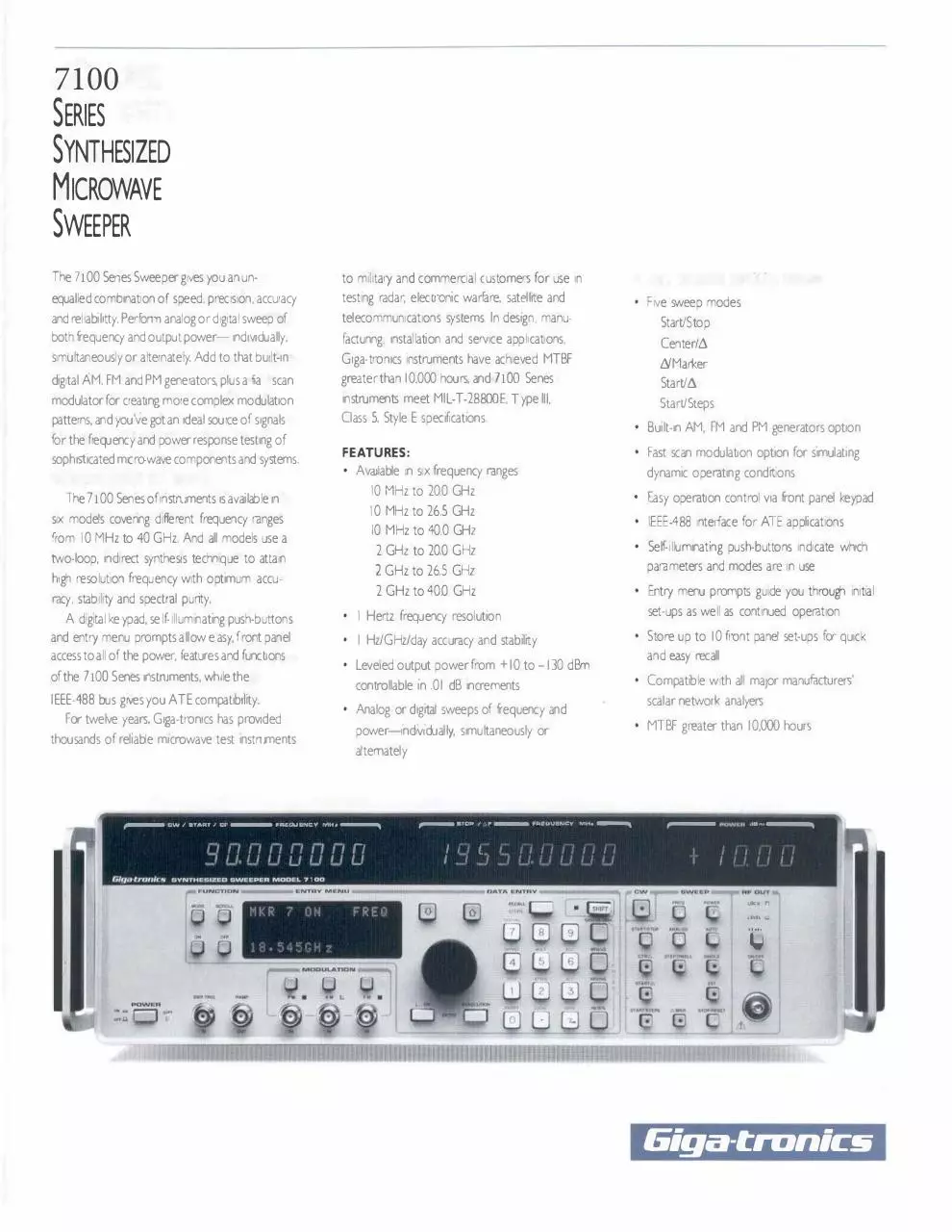
The 7100 Senes Sweeper gives you an un
to milrtary and commercial customers for use in
equalled combination of speed. precision, accuracy
testing radar, electronic warfare. satellrte and
and reliability. Perform analog or digital sweep of
telecommunications systems. In design, manu
both frequency and output power- 1nd1v1dually.
factunng, installation and seN1ce applications,
simultaneously or alternately. Add to that bu1lt-1n
Center/t.
Giga-trorncs instruments have achieved MTBF
digrtal AM. FM and PM generators. pius a fa scan
greater than 10.000 hours. and 7100 Senes
LYMarker
modulator for creating more complex modulation
instruments meet MIL-T-28800E, T ype Ill.
patterns, and you've got an ideal source of signals
Class 5, Style E specifications.
for the frequency and power response testing of
soph1sbcated microwave components and systems.
•
I Hz/GHz/day accuracy and stability
thousands of rehab:e microwave test instruments
•
IEEE-488 interface for ATE applications
Entry menu prompts guide you through 1nit1al
set-ups as well as continued operation
•
Store up to 10 front panel set-ups for quick
and easy recall
Leveled output power from + I 0 to -130 dBm
controllable 1n .0 I dB increments
For twelve years, Giga-tronics has proVlded
Easy operation control via front panel keypad
parameters and modes are in use
•
•
Fast scan modulation option for s1mulat1ng
• Self-illuminating push-buttons indicate which
I Hertz frequency resolution
IEEE-488 bus gives you ATE compat1b1hty.
•
Compatible wrth al maior manufacturers'
scalar network analyers
Analog or d1grtaJ sweeps of frequency and
power-;ndMdual�. simultaneously or
•
MTBF greater than I 0,000 hours
alternately
- "ll.UUl.;l\ll;Y Mlh --....
I I •Ir! I!,-! ;-/ r-/ I:
_-I J_/. I_/ I_/ u I_/ u u
GltJdfNlltl,'W • YNTHllal ZUD • w••P l. A
•
•
access to all of the power, features and functions
IH"'il' I t:I
•
2 GHz to 26.5 GHz
2 GHz to 40.0 GHz
racy. stability and spectral punty.
AM, FM and PM generators option
dynamic operating condrtions
2 GHz to 20.0 GHz
high resolution frequency with optimum accu
,,,__ t;W I
•
10 MHz to 26.5 GHz
10 MHz to 40.0 GHz
two-loop, indirect synthesis technique to attain
of the 7100 Senes instruments. while the
• Built-in
10 MHz to 20.0 GHz
six models covenng dife
f rent frequency ranges
and entry menu prompts allow e asy. f ront panel
Start/t.
Start/Steps
• Available 1n six frequency ranges
from I 0 MHz to 40 GHz. And all models use a
Five sweep modes
Start/Stop
FEATURES:
The 7100 Senes of instruments 1s available 1n
A d1grtal ke ypad, se lf-illuminating push-buttons
•
,...-u10••
:
I
'
I
1
•
- ....-.out••·n;Y
'
,
MH•
'
�
,.-- ..
uwe.H ...... --....
,
I
I
,
I
MOD•L 7 · 00
A•OUTl
lOCll "
11\oll.i...
·�
.....
"'• rl ..
'---'
POWllR
oi·JJ.
Giga-tranics
SPECIFICATIONS
ORDERING INFORMATION
SPECTRAL PURITY
MODEL NUMBERS AND FREQUENCY
Harmonics (up to maximum frequency):< -55 dBc,
0.05 to 40 GHz: < -25 dBc (< -20 dBc in
RANGES:
Frequency Range
10 MHz to 20.0 GHz
10 MHz to 26.5 GHz
10 MHz to 40.0 GHz
2 GHz to 20.0 GHz
2 GHz to 26.5 GHz
2 GHz to 40.0 GHz
AVAILABLE OPTIONS:
instruments to 40 GHz). 0.0 I to 0.05 GHz
add1t1on to the standard 10 MHz.
Option 17: Provides Fast Scan Modulation*'
Option 22: Moves the RF Output Connector from
26.5 GHz (< -55 dBc. 20 to 40 GHz. in
Power Line/Fan Rotation Related (dBc. CW Mode):
Frequency
to I k Hz
>I k H z
-SS
-ss
-SS
This option may decrease maximum output
Bto <20
-4S
20to 26.5
20to40
-55
-40
-39
-49
-49
�
Accessory A002: Instrument configured for
standard rack mounting with chassis slides.
Accessory A003: Instrument configured for
standard rack mounting without chassis slides.
Accessory A006: Extra extender board service kit
(One furnished with eac1 instrument).
Accessory AOIO: Extra operation and/or
maintenance manuals (One furnished with each
instrument; speofy type of manual when
ordering).
Note: See current G1ga-tron1cs price list for
possible new option and/or accessory
availability.
*Not available for instruments to 40 GHz
or down from a preset start frequency (F I )
to a preset stop frequency (F2)
-SS
-�
-
Bandwidth, CW Mode, All Power Levels):
Offset from Carner
Range(GHz) 30Hz IOOHz I kHz
.01 to< 2
-60
-7S
-80
-6S
-75
-80
-60
-65
-7S
-80
8to<20
20to 26.S
-ss
-65
-70
-70
20to40
-S4
-59
-69
-69
-7S
center frequency (CF)
I
-105
I
-100
- 9S
- 94
.3 to3 kHz
.OS to IS kHz
30
200
.01 to< 2
of Steps)sFB): Sweeps up or down from a
preset start frequency (F I ) through a preset
number of frequency steps
Sweep Functions:
SINGLE: A single cycle of preset sweep or (with
Pos t-detection Bandwidth
Range(GHz)
6MKR(FAsM, f. M,sFB): Sweeps up or
down from any preset marker (M,) to any
other preset marker (M,)
START/STEPS (FAsF I ±(Step Size x Number
AUTO: Continuous recycle of preset sweep
Residual FM (Hz. rms: CW Mode):
Frequency
through a preset sweep width (6F)
centered symmetrically about a preset
IOkHz IOOkHz
1
-75
-100
2to< 8
START/6 ( FAsF I ± 6FsFB): Sweeps up or
down from a preset start frequency (F I)
CTR/6 (FAsCF ± (6 F/2) sFB): Sweeps up
or down through a preset sweep width (6F)
Single-Sideband Phase Noise (dBdHz Noise
Fr equ e rcy
Sweep Modes:
ST ART/STOP (FAsF I f. F2sFB): Sweeps up
-SS
-ss
-so
AM. FM and PM envelopes
connector adaptors (F-F and M-F).*
locked at each step during dwell time
<300Hz
power by as much as 2 cB*
cables (18 and 72 inch lengths) and 2 output
Accuracy and Stability: Same as 1n CW when
300Hz
Range(GHz)
frequency resolution
Dwell Time: May be set 1n I 0 msec increments
from approximately I 0 msec to 200 sec
Offset from Carner
-4S
-so
Accessory AOO I : Cable Kit consisting of 2 low loss
instrument)
Step Size: Any increment within the instrument's
40 GHz, in instruments to 40 GHz)
2to < 8
AVAILABLE ACCESSORIES:
instrument) to FB (maximum frequency of the
Nonharmon1cs:<-SS dBc (< -49 dBc. 20 to
.01 to< 2
two built-in function generators for generating
Sweep Range: FA (minimum frequency of the
instruments to 40 GHz)
the instrument's front panel to its rear panel.
Option 24: Provides a built-in pulse generator and
size and dwell time are selectable.
Subharmonics: None 1n instruments to 20 or
Option 11: Allows external time base of 5 MHz in
DIGITAL FREQUENCY SWEEP
A precs1on d1g1tal (step and dwell) frequency sweep
acquires a lock at each discrete frequency step. Step
2to< 8
20
ISO
8 to <20
40
300
20 to 26.5
60
4SO
20to40
80
600
STOP activated) a single preset step,
1nit1ated by manual operation of a front
panel push-button
EXT: A single cycle of preset sweep or (w,th
STOP activated) a single preset step, 1nit1ated
by each trigger from an external source
EXT STOP (External Step): A single step of a
preset sweep 1nit1ated by each trigger from
an external source
RF FREQUENCY PARAMETERS
AND OPERATIONAL MODES
All variable RF frequency parameter values may be
set via the GPIB or from the front panel by keyboard,
d1gi-dial or up/down push-button entry. Frequency
sweep may be operated simultaneously or alternately
with power sweep.
CW OPERATION
Range: 0.0 I or 2 to 20, 26.5 or 40 GHz
(see Ordering Information)
Resolution: I Hz (2 Hz above 20 GHz in
instruments to 40 GHz)
Accuracy and Stability: Identical to time base
oscillator
Time Base (Internal): I 0 MHz
Aging Rate: <I
x
I o-•/day after 72 hours
continuous operation
Temperature Stability: < c:: 2
x
Io- 10/°C
(O to +50°C)
Time Base (External): I 0 MHz (5 or I 0 MHz.
switchable, with Option
11) ± I x Io-• or
better
Switching Time: <50 msec (20 msec, typical) to
w1th1n specified frequency accuracy
STOP/RESET: Stops sweep when activated by
front panel push-button to allow manual
tun:ng of frequency at any point 1n the
sweep. Second depression of push-button
resets sweep to 1nit1al conditions.
RF OUTPUT POWER PARAMETERS
AND OPERATIONAL MODES
ANALOG FREQUENCY SWEEP
Fast. continuous analog frequency sweep 1s self
generated w1th1n the instrument. it 1s phase-lock
corrected at each start and band-crossing frequency.
Sweep Range: FA (minimum frequency of tre
1ns:rument) to FB (max.mum frequency of the
1nstn;men:)
Sweep Time(Any Sweep Mode): 2 msec to
200 sec 1n five ranges Minimum sweep time s
determined by the sweep width swep: and the
max1r1um sweep speed
Res oluti on
Range
2 rnsec to 20 rnse(
10 µsec
20 rnsec :o 200 rnsec
IOOµsec
200rnsec to
2
20
sec to
sec
Msec
20 sec
IOrnsec
2
sec:o 200
sec
100 rr.sec
M1n:mum Sweep W.dth: I MHz
Maximum Sweep Speed: 600 MHz/msec
Band Crossing Dead Time (at 2. 8. 20 and
28GHz): 50 msec. nom1na
Start Frequency Accuracy (Any Sweep Mode):
±0.5 MHz
Sweep Width Resolution(Any Sweep Mode):
0 I % of sweep w1dt�(0.2% above 20GHz .n
instruments to 40GHz)
Sweep L1neanty (Re1at1ve to Linear RAMP OUT
Voltage. Sweep Time �I 00 msec. Any Sweep
Mode): ± I% of sweep width or ±50 MHz
( ± 2% or ± I 0 0 MHz 1n instruments to
40GHz). whichever is less
Markers: 8 frequency 1dent1fy1ng markers (intensity
or amplitude) ind1v1dually se:ectable from tre
front panel or via theGPIB
Marker Reso ut1on: Sweep width/4.000
Marker Accuracy: Same as sweep linearity
except marker may vary ± 25 rrV relative
to linear 0 to I 0 V RAMP OUT
Amplitude Markers: Approximately - 3 dB
change in RF output power during analog
frequency sweep markers
Sweep Modes: Sar1e as Frequency D g1tal Sweep
Modes except t�e START/STEPS mode is
de eted
Sweep Functions: Same as Frequency D·g tal
Sweep Functions
All variable RF output power parameter values may
be set via the GPIB or from the front panel by
keyboard. d1g1-d1al or up/down push-button entry.
Power sweep may be operated s.multaneously or
alternately with frequency sweep.
RF OUTPUT POWER
Maximum Leveled Output: +I 0 dBm(.n
instruments to 40GHz: +I 0 dBm. 0.0I
to 20GHz: +5 dBm. 20 to 35GHz.
+2 dBm. 35 to 40GHz)
Incremental Level Range: -20 to + 15 dBm
Resolution: 0.0 I dB. entry and display to
-99.99 dBm(d1splay 1sO. I dBat
S-100.0d�m)
Minimum Output Level: -130 dBm ( -110 dBm 1n
instruments to 26.5 or 40GHz)
RF Off: Typ1cally attenuates a 0 dBm signal to
< - 140 dBm at the output connector
Output Accuracy (Internally Leveled. CW or
frequency sweep rrode. AM Of0: ± I dB to
20GHz. ± 2 dB to 40GHz( ±0. I dB per IOdB
attenuation step)
Output Flatness: Included m accuracy
Output Switching Time: Typ•cally < I msec
(20 'T1Sec with attenuator change)
Output Impedance: 50 ohms. nominal
Output SWR: <2: I
External Leveling: Output power 'nay be
externally leveled by pos1t1ve or negative ZBS
detectors or power meters
DIGITAL POWER SWEEP
A precision d1g1tal (step ano dwell) power sweep
acquires a level at each discrete power step. Step size
and dwell time are selectable
Sweep Range: LA(minimum output level of the
instrument) to LB(max1mum output evel of the
instrument)
Step Size: Any mutt pie of 0.0 I dB up to
instrument's maximum sweep range
Dwell Time: May be set m I 0 msec increments
from approximately I 0 msec to 200 sec
Accuracy: Same as in non-swept mode when
leveled at each step during dwell time
Sweep Modes:
START/STOP(LAsl I -#. L2sLB): Sweeps up
or down from a preset start level(LI ) to a
preset stop level(L2)
START/6(LAsL I ±6LsLB) Sweeps up or
down from a preset start level (L I ) through a
preset sweep width (.0.L)
CTR/6 (LAsCL ±(6U2)sLB): Sweeps up or
down through a preset sweep width (6L)
centered symmetrically about a preset
center leve1(CL)
START/STEPS(LAsL I ±(Step Size x Number
of Steps)sLB): Sweeps up or down from a
preset start level (L I) through a preset
number of level steps
Sweep Functions: Same as Frequency Digital
Sweep Funct ons
ANALOG POWER SWEEP
Fast. continuous analog power sweep 1s self
generated within the instrument.
Sweep Range: 20 dB. maximum. up or down.
w1th1n incremental level range (from maximum
output power to -20 dBm. minus attenuator
setting)
Sweep Time(Any Sweep Mode): 2 msec to
200 sec m five ranges Minimum sweep time is
determined by tne sweep width swept and the
maximum sweep speed.
Range
Resolution
2 rnsec to 20 rnsec
20 rnsec to 200 rnsec
200 rnsec to
2
20
secto
2 sec
IOµsec
IOOµsec
I rnsec
20
sec
IOrnsec
sec to 200
sec
IOOmsec
Minimum Sweep Width: 0.0 I dB
Maximum Sweep Speed: I dB/msec
Start Level Accuracy(Any sweep mode): ±0.5 dB
Sweep Level Resolution (Any sweep mode):
0.01 dB
Sweep Level Lmeanty(Any sweep mode): ±5%
of sweep width
Sweep Modes: Same as Output Power D1g1tal
Sweep Modes except there 1s no START/STEPS
mode
Sweep Functions: Same as Frequency Analog
Sweep Functions
MODULATION PARAMETERS
AND OPERATIONAL MODES
Modulation parameter values may be set via the GPIB
or from the front panel by keyboard. d1g1-d1al or
up/down push-button entry. Modulation
spec1fcat,ons apply in the CW mode and are operable
in the sweep modes.
AMPLITUDE MODULATION (AM)
Amplitude Modulation spec1ficat1ons ap:>ly for
waveforms whose envelope peak 1s at least I dB
below maximum specified output power when the
instrument 1s internally leveled, FM and PM off. AM
may be operated simultaneously with FM.
AM Envelope Parameters:
Depth:
Range: 0 to at least 90%
Resolution: 0.1 % increments
Accuracy: ±5%
Readout: 3d1g1ts
Resolution: 0.1 %
Bandwidth (30% depth): DC cou�led. 3 dB
points > 50 kHz
Frequency Response (Flatness reld1ve to I kHz
rate at 30% depth): ±0.2 dB (0.5 dB for
instruments to 40 GHz). DC to I 0 kHz
Harmonic Distortion (Relative to externally
supplied AM envelope): 2% (1% typical).
s50% depth s 1 kHz rate: 10%. sSO%
depth, sSO kHz rate
Incidental Phase Modulation (Rates s I 0 kHz.
30% depth, SO Hz to 15 kHz measurement
bandwidth): <0.2 radians, peak, typical
Incidental FM: Incidental Phase Modu lation X
AM rate
.
Externally Supplied AM Envelope
Waveform: Any waveform compatible with
bandwidth considerations
Rate: DC to I 00 kHz
Sens1t1v1ty: I V, peak. for I 00% depth
Input Impedance: 600 ohms, nominal
FREQUENCY MODULATION (FM)
PULSE/SQUARE WAVE MODULATION (PM)
Frequency Modulation spec1ficat1ons apply with AM
and PM off. FM may be operated simultaneously with
AM or PM.
Pulse modulation specifications apply with AM and
FM off. PM may be operated simultaneously with FM.
FM Envelope Parameters
Max Deviation (Wide Mode): I 0 MHz. peak
(20 Mhz. peak, above 20 GHz 1n instruments
to4 0 GHz)
Flatness: ± I dB for rates from I 0 Hz to
I MHz: ± 3 dB from I to S MHz
Residual FM (50 Hz to 15 kHz post-detection
bandwidth): <3 kHz rms, typ1cal (<6 kHz
rms. typical. above 20GHz 1n instruments
to40GHz)
Max Deviation (Narrow Mode): The lesser of
I 00 x FMOO or I 0 MHz, peak (200 x FMOO or
20 MHz, peak. above 20 GHz in instruments
to40GHz)
Flatness: ± I dB for rates from 20 k Hz to
I MHz: ±3dB from I toSMHz
Residual FM: Same as CW (see Spectral
Purity)
Accu racy: ± 5%
Readout: 3 digits
Resolution: I 0 kHz
D1stort1on: <5%
Incidental AM: < ± 0.2%/MHz of deviation
Externally Supplied FM Envelope
Waveform: Any waveform compatible with
bandwidth considerations
Rate: I 0 Hz to S MHz
Sens1t1vrty: I V, peak. for maximum dev1at1on
Input Impedance: SO ohms. nominal
Internally Generated FM Envelope
(Option 24)
Waveform: Sine, square or triangle wave
Rate: I 0 Hz to I MHz
Resolution: I Hz
Accuracy: ±0.0 I Hz
Internally Generated AM Envelope
(Option 24)
Waveform: Sine. square or triangle wave
Rate: I Hz to I 00 kHz
Resolution: I Hz
Accuracy: ± ?·O I Hz
FAST SCAN MODULATION (FSM)- OPTION 17 (Instruments to 20 or 26.S GHz only)
The fast scan modulator, a d1g1tally controlled and
linearized PIN diode attenuator 1nsertec between the
instrument's leveling loop and output attenuator,
allows the independent. simultaneous control of AM
and PM.
Scan Mode (DC coupled):
.
and 20GHz.
Frequency Response: DC to 150 k Hz. sine wave
Rise/Fall T1rrie Response to Step Input: O.S µ.sec up
to 40dB step
Delay Time: 0.5 µ.sec. typical
Sens1t1v1ty: 0.1 V/dB (I 0 dB/V)
Input Impedance: SO ohms. nominal
Orv'Off Ratio >80 dB
Rise/Fall Times: < I 0 nsec
Overshoot. Undershoot and Ringing: ± 2 dB,
maximum
Settling Time (to w1th1n I dB): < I 00 nsec
Leveled Pulsed Output Power (Referenced to
leveled CW output power): ± 0.5 dB. typical,
�I 00 nsec widt h : ± I dB, typical. < I 00 nsec
width
Externally Supplied PM Envelope
One PM envelope produced by each pulse supplied
Repetition Rate: 5 Hz to 5 MHz. leveled output:
DC to I 0 MHz. unleveled output
Pulse Delay (Output envelope leading edge
referenced to input pulse leading edge):
SO nsec, ty:>1cal
Input Pulse Required: Positive or negative-going
TIL level pulse, �50 nsec wide (leveled output):
>20 nsec wide (unleveled output)
Internally Generated PM Envelope (Option 24)
Repetition Ra:e
Range
Resolution
5 Hzto 100 Hz
0.1 Hz
I
Hz
I kHz to IOkHz
10
Hz
IOkHzto IOOkHz
100
Hz
I MHz
I
kHz
100 Hz to
IOOkHzto
I kHz
Accuracy: ± 0.02% of range maximum value
jitter: Same as instrument time base
Pulse Delay (Referenced to sync output)
Range: 0 to 2 sec
Resolution: I 0 nsec
Accuracy: ± I% of setting or 20 nsec,
whichever is greater
Jitter: 0.0 I% of setting or I 00 psec.
whichever 1s greater
Pulse Width
Range: 50 nsec to 2 sec
Resolution: I 0 nsec
Accuracy: ± I % of setting or 20 nsec.
whichever 1s greater
Jitter: 0.0 I% of setting or I 00 psec.
whichever 1s gr eater
Externally Triggered PM Envelope
(Option 24)
One PM envelope produced by each trigger
supplied
Repet1t1on Rate: 5 Hz to 5 MHz
Pulse Delay: Set by internal delay control (see
AM Mode (AC coupled):
Dynamic Range:40 dB. minimum
Linearity (at cal points): ± 0 6 dB (0 to 20 dB).
± I dB (20 to SO dB). Unless otherwise
requested, cal points are I, 4, 8. Ii, 14, 16, 18
PM Envelope Parameters
Modulation Depth: 0 to 90%
RF Output Level: Approx. 11 dB below generator
setting
Frequency Response: I 0 Hz to SO kHz
Total Harmonic D1stort1on: 5%. max (2% typical)
at 80% modulation; 10%, max(5% typical) at
30% modulation
Input Sens1t1v1ty: I V. p-p. for 50% modulation at
I kHz
Input Impedance: 50 ohms. nominal
Insertion Loss: 5 dB, max (3dB typical). by-passed
when not i n use
above)
Pulse Width: Set by internal width control (see
above)
Input Tngger F.equ1red: Pos1t1ve or negative
going TIL level trigger pulse, �25 nsec wide
d
rd
13
)(
0
()
GENERAL SPECIFICATIONS
Remote Interface: IEEE STD 488-1978-All
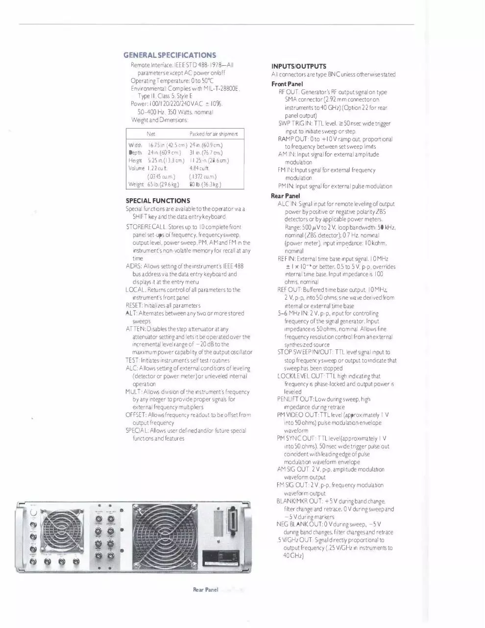
INPUTS/OUTPUTS
parameters except AC power on/off
All connectors are type BNC unless otherwise stated
Operating Temperature: 0 to S0°C
Front Panel
Environmental: Complies with MIL-T-28800E,
RF OUT: Generator's RF output signal on type
Type Ill, Class S. Style E
Power: 100/1201220/240VAC
SMA connector (2.92 mm connector on
±: 10%.
instruments to 40 GHz)(Opt1on 22 for rear
S0-400 Hz, 3SO Watts, nominal
panel output)
Weight and D1mens1ons:
Net
Wd�h
Depth
Height
Volume
SWP TRIG IN: TIL level. �so nsec wide trigger
input to in1t1ate sweep or step.
RAMP OUT: 0 to + I 0 V ramp out. proportional
Packed for air shipment
16.751n.(42.Scm.) 24 m. ( 609cm.)
24 in. (60.9 cm.)
5.25 1n.( 13.3 cm.)
1.22 cu.ft.
(.0345 cu.m )
Weight 65 lb. (29.6 kg.)
to frequency between set sweep limits
31 m. (76.7 cm.)
11.25 1n. (28.6 cm.)
AM IN: Input signal for external amplitude
4.84 cu.ft.
FM IN: Input signal for external frequency
(.1372 cu.'n.)
modulation
I
80 lb. (363 kg.)
modulation
PM IN: Input signal for external pulse modulation
Rear Panel
SPECIAL FUNCTIONS
Special fur.ctions are available to the operator via a
SHIFT key and the data entry keyboard.
STORE/RECALL: Stores up to I 0 complete front
ALC IN: Signal input for remote leveling of output
power by positive or negative polarity ZBS
detectors or by applicable power meters.
Range: SOO µV to 2 V, loop bandwidth: SO kHz.
panel set-ups of frequency, frequency sweep,
nominal (ZBS detector): 0.7 Hz, nominal
output level. power sweep. PM. AM and FM in the
(power meter), input impedance:
I 0 kohm.
·
instrument's non-volat1le memory for recall at any
time
nominal
REF IN: External time base input signal. I 0 MHz
ADRS: Allows setting of the instrument's IEEE 488
bus address via the data entry keyboard and
displays 1t at the entry menu
±: I x I o - ' or better, 0.5 to S V, p-p, overrides
internal time base. Input impedance is I 00
ohms, nominal
LOCAL: Returns control of all parameters to the
instrument's front panel
REF OUT: Buffered time base output. I 0 MHz.
2 V, p-p, into SO ohms. sine wave derived from
RESET: lnit1al1zes all parameters
internal or external time base
ALT: Alternates between any two or more stored
sweeps
5-6 MHz IN: 2 V, p-p, input for controlling
frequency of the signal generator. Input
ATIEN: Disables the step attenuator at any
impedance 1s 50 ohms. nominal. Allows fine
attenuator setting and lets it be operated over the
frequency resolution control from an external
incremental level range of -20 dB to the
synthesized source
maximum power capab1l1ty of the output osollator
STOP SWEEP IN/OUT: TIL level signal input to
TEST: Initiates instrument's self test routines
stop frequency sweep or output to indicate that
ALC: Allows setting of external cond1t1ons of leveling
sweep has been stopped
(detector or power meter) or unleveled internal
operation
LOCK/LEVEL OUT: TIL high indicating that
frequency 1s phase-locked and output power 1s
MULT: Allows d1v1s1on of the instrument's frequency
by any integer to provide proper signals for
leveled
PENLIFT OUT: Low during sweep, high
impedance during retrace
externa frequency multipliers
OFFSET: Allows frequency readout to be offset from
PM VIDEO OUT: TIL level (approximately I V
into SO ohms) pulse modulation envelope
output frequency
SPECIAL: Allows user defned and/or future special
waveform
PM SYNC OUT: TIL level (approximately I V
funct;ons and features
into SO ohms). 50 nsec wide trigger pulse out
co1nc1dent with leading edge of pulse
modulation waveform envelope
AM SIG OUT: 2 V, p-p. amplitude modulation
•
•
!i
•
�i·
@ � t!)
ii
00
•
•
waveform output
.;
FM SIG OUT: 2 V, p-p, frequency modulation
waveform output
BLANK/MKR OU T: + 5 V during band change,
w
If
•
11111
Rear Panel
filter change and retrace, 0 V during sweep and
-S V during markers
NEG BLANK OUT: 0 V during sweep, -S V
during band changes, filter changes and retrace
.S V/GHz OUT: Signal directly proportional to
output frequency (.2S V/GHz in instruments to
40GHz)
Download 7100 brochure
7100_brochure.pdf (PDF, 586.44 KB)
Download PDF
Share this file on social networks
Link to this page
Permanent link
Use the permanent link to the download page to share your document on Facebook, Twitter, LinkedIn, or directly with a contact by e-Mail, Messenger, Whatsapp, Line..
Short link
Use the short link to share your document on Twitter or by text message (SMS)
HTML Code
Copy the following HTML code to share your document on a Website or Blog
QR Code to this page

This file has been shared publicly by a user of PDF Archive.
Document ID: 0001871901.