Report openwrt (PDF)
File information
This PDF 1.5 document has been generated by TeX / pdfTeX-1.40.16, and has been sent on pdf-archive.com on 09/05/2018 at 14:51, from IP address 130.192.x.x.
The current document download page has been viewed 1268 times.
File size: 700.56 KB (28 pages).
Privacy: public file


File preview
Politecnico di Torino
C.A.R.S.
Center for Automotive Research and Sustainable
mobility
Implementation of a
VoIP-enabled V2I
communication based on
802.11a
Author:
Marco Malinverno
Giuseppe Avino
Supervisor:
Carla Chiasserini
Claudio Casetti
April 18, 2018
1
Introduction
This brief document has been created to give the detailed hardware and
software architecture’s description of the solution we implemented in a University project. All the procedure and configurations will be presented and
explained in order to provide step-by-step guides and to let other replicate
each aspect of the network architecture. For questions, comments or doubts,
send an email to:
marco.malinverno@polito.it
giuseppe.avino@polito.it
1.1
Network Architecture Description
Figure 1: Network Architecture
The architecture that will be created can be see in Fig 1. The main
router (the one that will act as Access Point), will act as DHCP server and
as Asterisk server. The vehicles is equipped with the MicroAutoBox II control
unit, and its network capability will be extended to wireless by plugging its
Ethernet port to our Routed Client. This will be the same as plugging the
control unit to a wifi dongle. The device used in the vehicle (Alix3d3) comes
with embedded audio in-out with two 3.5mm Jack. An audio splitter will be
connected to those port and will provide a unique input (to match modern
headsets requirements). A simple Baresip client will be created directly in
1
the Routed Client. A terminal directly plugged to the AP may run the
MicroAutoBox II manager and connect the user with the vehicle’s control
unit, and a Linphone client can be connected to the AP to communicate
with Baresip present in the Routed Client. From a network topology point
of view, all the nodes will be in the 192.168.1.0/24 subnet.
1.2
Hardware used
In order to enable the communication between the control unit and the engineer desk, additional hardware is needed, since the MicroAutoBox only come
with an Ethernet port. The devices used are two Alix board:
• PC Engines Alix 3d31 : to be used in the vehicle. It is equipped with two
3.5mm Jack input that will be used to enable the voice communication
in the vehicle.
• PC Engines Alix 3d22 : to be used at the box-side.
The two mainboards do not come with built-in Wi-Fi modules, so they
have been equipped with a Ubiquiti XR53 .
Two antennas, working in the 5GHz domain are used:
• Vehicle antenna: NET-WL-ANT5458-04SCN4
• Box antenna: Horizon Maxi 12dB5
Finally, to load the OS in the boards, two 8GB PC Engines Compact
Flash6 are used.
1
https://www.pcengines.ch/alix3d3.htm
https://www.pcengines.ch/alix3d2.htm
3
https://dl.ubnt.com/xr5 datasheet.pdf
4
https://www.solwise.co.uk/wireless-outdoorantenna-58-vehicle-04scn.htm
5
http://www.ted.net.pl/anteny/antena-dookolna-interline-horizon-maxi-12dbi-5ghz-54-5-8ghz.html
6
https://www.pcengines.ch/cf8slc.htm
2
2
1.3
1.3.1
Software used
Operating Systems
The two Alix boards are equipped with the latest (at the time of writing)
OpenwWrt distribution (Lede 17.01.4). In order to install OpenWrt in the
two devices it is necessary to download the .img file from the Downloads area
in the OpenWrt web page and then, using a CF reader, write the image in the
CF support. To do so, we used the Startup Disk Creator utility of Ubuntu.
The image file we used for our Alix board, as well as other information and
the full guide to install the OpenWrt distro can be found at:
https://openwrt.org/toh/hwdata/pcengines/pcengines alix3d2
1.3.2
VoIP software
In order to enable a voice communication between the vehicle and the box,
we need a simple VoIP architecture in the LAN we’re going to create. This
architecture is composed by a PBX server (to be issued somewere in the
network, possibly ’in the middle’ between the vehicle and the box) and of
two VoIP clients. One of those clients should be installed in the Alix present
on the vehicle, while the other on a terminal used by the engineering team
in the box. The PBX server used here is Asterisk7 , while the VoIP client will
be Baresip8 (for the vehicle) and Linphone9 (for the box).
2
Step-by-step guides
In this part, the step-by-step guides to reach the configuration in Figure 1
are presented. The tutorials are created using documentation present on the
internet (OpenWrt how-tos and threads, blogs, forums etc.) as well as with
direct experience. This guide will show how to configure the devices using
the Web GUI. Moreover, all the config files will be showed.
3
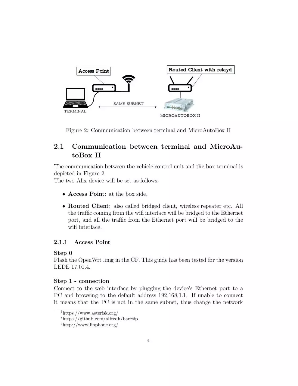
Figure 2: Communication between terminal and MicroAutoBox II
2.1
Communication between terminal and MicroAutoBox II
The communication between the vehicle control unit and the box terminal is
depicted in Figure 2.
The two Alix device will be set as follows:
• Access Point: at the box side.
• Routed Client: also called bridged client, wireless repeater etc. All
the traffic coming from the wifi interface will be bridged to the Ethernet
port, and all the traffic from the Ethernet port will be bridged to the
wifi interface.
2.1.1
Access Point
Step 0
Flash the OpenWrt .img in the CF. This guide has been tested for the version
LEDE 17.01.4.
Step 1 - connection
Connect to the web interface by plugging the device’s Ethernet port to a
PC and browsing to the default address 192.168.1.1. If unable to connect
it means that the PC is not in the same subnet, thus change the network
7
https://www.asterisk.org/
https://github.com/alfredh/baresip
9
http://www.linphone.org/
8
4
card address. It can be done either through the Linux connection manager
(edit Wired connection → IPv4 Settings → Method: Manual → Address:
192.168.1.2, Netmask: 24, Gateway: 192.168.1.1) or simply doing:
$ sudo i f c o n f i g <i n t e r f a c e > 1 9 2 . 1 6 8 . 1 . 2 / 2 4
where ’interface’ is the Ethernet interface’s name (usually eth0). Once connected, login with username ’root’ and go to ’configure password’ (configuring
a password will allow SSH access to the device).
Step 2 - wireless card configuration
Go to the menu Network → Wireless and click edit beside the Radio interface
you want to configure (e.g. Generic MAC80211 802.11abg (radio0)). In the
General Setup tab click to Enable to enable the interface. Now select the
Band (e.g. 5GHz) and the Channel.
NOTE: do not choose ’auto’ in the channel method, since it seems to
create problem. Use instead a channel that you are sure it suits your
Wi-Fi card. For Ubiquiti XR5 available and tested channels are: 36,
40, 44, 48, 149, 153, 157, 161, 165.
Go to Advanced Settings tab and configure the Country Code. Finally
in the section ’Interface Configuration’, tab General Setup, set your ESSID
(the name of the wireless network), set Mode to ’Access Point’ and leave all
the other configuration as they are. In the tab Wireless Security, eventually
choose an Encryption mehod (e.g. WPA2-PSK). a Cipher and a password.
Step 3 - interface configuration
Go to Network → Interfaces and click ’edit’ beside the interface LAN. Here
be sure that the Protocol is set to ’Static address’. In the Physical Settings
tab, check that the Bridge Interfaces option is ticked and that it bridges
between Ethernet Adapter and Wireless Network. Finally control that the
DHCP server is enabled (so, leave the ’Ignore interface’ option unchecked).
This device will assign the IP address to each node in the nework. ’Save and
apply’ and now you can unplug the cable and plug back again as a DHCP
client.
5
NOTE: If you want to fix IP addresses of clients connected to the
AP, just go to tab Network → DHCP and DNS, in the section ’Static
Leases’ click on ’Add’ and compile the section by specifying ’Lease
time’ to ’infinite’.
Step 4 - firewall
Go to tab Network → Firewall and in the section ’Zones’ put all the values
for the ’lan’ zone to accept.
Configuration Files
/etc/config/network
c o n f i g i n t e r f a c e ’ loopback ’
o p t i o n ifname ’ l o ’
option proto ’ s t a t i c ’
option ipaddr ’ 1 2 7 . 0 . 0 . 1 ’
o p t i o n netmask ’ 2 5 5 . 0 . 0 . 0 ’
config globals ’ globals ’
o p t i o n u l a p r e f i x ’ fd8b : 2 0 6 d : 2 3 9 c : : / 4 8 ’
c o n f i g i n t e r f a c e ’ lan ’
o p t i o n type ’ b r i d g e ’
o p t i o n ifname ’ eth0 ’
option proto ’ s t a t i c ’
option ipaddr ’ 1 9 2 . 1 6 8 . 1 . 1 ’
o p t i o n netmask ’ 2 5 5 . 2 5 5 . 2 5 5 . 0 ’
option ip6assign ’60 ’
/etc/config/wireless
c o n f i g w i f i −d e v i c e ’ r a d i o 0 ’
o p t i o n type ’ mac80211 ’
o p t i o n hwmode ’ 1 1 a ’
6
o p t i o n path ’ p c i 0 0 0 0 : 0 0 / 0 0 0 0 : 0 0 : 0 c . 0 ’
o p t i o n c o u n t r y ’ IT ’
option channel ’153 ’
c o n f i g w i f i −i f a c e ’ d e f a u l t r a d i o 0 ’
option device ’ radio0 ’
o p t i o n mode ’ ap ’
o p t i o n s s i d ’ AccessPoint ’
o p t i o n key ’ password ’
o p t i o n network ’ lan ’
o p t i o n e n c r y p t i o n ’ psk2 ’
o p t i o n wmm ’ 0 ’
/etc/config/dhcp
c o n f i g dnsmasq
option
option
option
option
option
option
option
option
option
option
option
option
option
option
domainneeded ’ 1 ’
boguspriv ’1 ’
l o c a l i s e q u e r i e s ’1 ’
rebind protection ’1 ’
rebind localhost ’1 ’
local ’/ lan / ’
domain ’ lan ’
e xpand hosts ’ 1 ’
authoritative ’1 ’
readethers ’1 ’
l e a s e f i l e ’ / tmp/ dhcp . l e a s e s ’
r e s o l v f i l e ’ / tmp/ r e s o l v . c o n f . auto ’
l o c a l s e r v i c e ’1 ’
nonwildcard ’0 ’
c o n f i g dhcp ’ lan ’
o p t i o n i n t e r f a c e ’ lan ’
option s t a r t ’100 ’
option l i m i t ’150 ’
7
option
option
option
option
l e a s e t i m e ’12h ’
dhcpv6 ’ s e r v e r ’
ra ’ server ’
ra management ’ 1 ’
c o n f i g dhcp ’ wan ’
o p t i o n i n t e r f a c e ’ wan ’
option ignore ’1 ’
c o n f i g odhcpd
option
option
option
c o n f i g host
option
option
option
option
option
’ odhcpd ’
maindhcp ’ 0 ’
l e a s e f i l e ’ / tmp/ h o s t s / odhcpd ’
l e a s e t r i g g e r ’ / u s r / s b i n / odhcpd−update ’
name ’ example−s t a t i c −l e a s e ’
dns ’ 1 ’
mac ’ 0 0 : 0 0 : 0 1 : 0 0 : 0 0 : 0 1 ’
ip ’192.168.1.100 ’
leasetime ’ infinite ’
/etc/config/firewall
config defaults
option syn flood ’1 ’
o p t i o n i n p u t ’ACCEPT’
o p t i o n output ’ACCEPT’
o p t i o n f o r w a r d ’ACCEPT’
c o n f i g zone
o p t i o n name ’ lan ’
l i s t network ’ lan ’
o p t i o n i n p u t ’ACCEPT’
o p t i o n output ’ACCEPT’
o p t i o n f o r w a r d ’ACCEPT’
8
Download Report openwrt
Report_openwrt.pdf (PDF, 700.56 KB)
Download PDF
Share this file on social networks
Link to this page
Permanent link
Use the permanent link to the download page to share your document on Facebook, Twitter, LinkedIn, or directly with a contact by e-Mail, Messenger, Whatsapp, Line..
Short link
Use the short link to share your document on Twitter or by text message (SMS)
HTML Code
Copy the following HTML code to share your document on a Website or Blog
QR Code to this page

This file has been shared publicly by a user of PDF Archive.
Document ID: 0001873133.