Atomenergoproekt BN 800 NPP (PDF)


File preview
Joint Stock Company
St. Petersburg Research
and Design Institute
ATOMENERGOPROEKT
(JSC SPbAEP)
BN-800 NPP
2011
Contents
Introduction 3
New generation nuclear power plant
featuring BN-800 reactor 7
BN-800 NPP: heat flow chart 9
BN-800 reactor 10
Design approaches to safety systems of NPP
with BN-800 reactor 12
Diagrams of radioactive waste handling
at NPP with BN-800 15
NPP protection from external impacts 16
Radiation impact of NPP with BN-800 reactor 18
SPbAEP today 20
Contact information 20
JSC SPbAEP today:
- more than 80 years of successful work;
- more than 1700 world-class specialists;
- Quality Management System ISO 9001;
- unique projects implemented in 19 countries;
- participation in designing 118 power stations,
including 18 nuclear power plants.
Introduction
Role of BN-800 concept in the development
of fast reactor technologies
The current state of fast reactor technologies (including projections for the next 10 to 15 years)
makes the erection of Power Unit 4 of Beloyarskaya NPP (BNPP) particularly important for:
yy further enhancement of safety aspects;
yy demonstration of competitiveness of the technology;
yy optimization of the closed-loop fuel cycle as a basis of nuclear energy production in future and development of non-proliferation strategies;
yy efficient implementation of weapon-grade plutonium recycling program based on the inherently
local technologies which reduce the risks involved in the use of new MOX-fuel at existing nuclear
power plants;
yy satisfying local demand for energy.
Below are described the main ways of implementing the aforesaid fast-reactor technologies.
BN-800 as a basis of further development of the technology
of BN-800 concept in the enhancement of NPP safety and
competitiveness
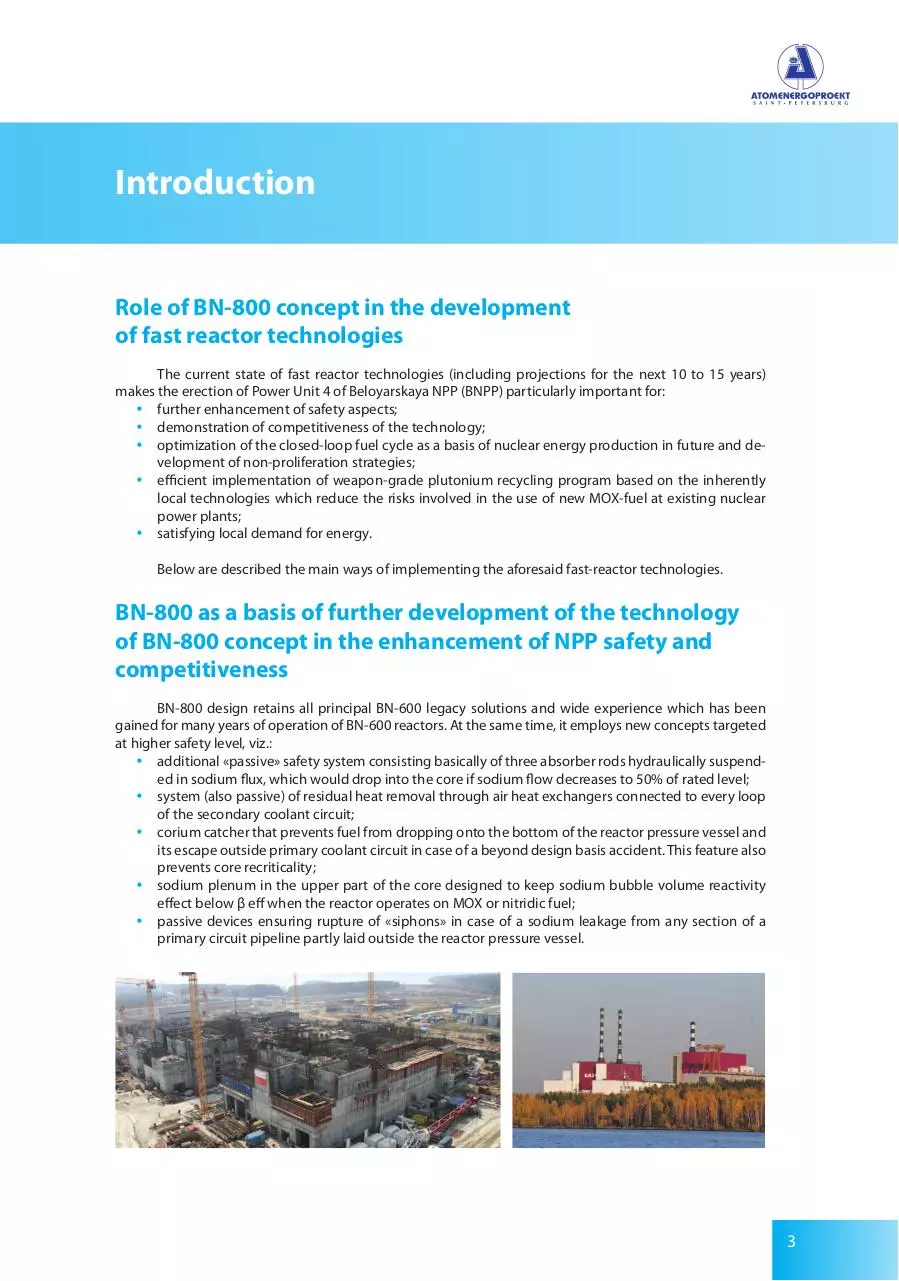
BN-800 design retains all principal BN-600 legacy solutions and wide experience which has been
gained for many years of operation of BN-600 reactors. At the same time, it employs new concepts targeted
at higher safety level, viz.:
yy additional «passive» safety system consisting basically of three absorber rods hydraulically suspended in sodium flux, which would drop into the core if sodium flow decreases to 50% of rated level;
yy system (also passive) of residual heat removal through air heat exchangers connected to every loop
of the secondary coolant circuit;
yy corium catcher that prevents fuel from dropping onto the bottom of the reactor pressure vessel and
its escape outside primary coolant circuit in case of a beyond design basis accident. This feature also
prevents core recriticality;
yy sodium plenum in the upper part of the core designed to keep sodium bubble volume reactivity
effect below β eff when the reactor operates on MOX or nitridic fuel;
yy passive devices ensuring rupture of «siphons» in case of a sodium leakage from any section of a
primary circuit pipeline partly laid outside the reactor pressure vessel.
3
Introduction
The above provisions resulted in the high resistance of the reactor to beyond-design-basis accidents.
This is why practical experience in operating BN-800 safety systems is considered as an important contribution to the development of BN technologies. New solutions such as an increase in rated heat power (from
1470 MW in BN-600 to 2100 MW in BN-800) without any substantial changes in the RPV design, and the use
of steam/steam reheating, reduction in number of auxiliary systems and their improvement, etc., lead to a
considerable decrease in the metal intensity of the project (from 4.3 t/MW (therm.) in BN-600 to 2.7 t/MW
(therm.) in BN-800), which, in turn, enhances its competitiveness.
Role of BN-800 concept in the implementation of fast reactor
fuel cycle and recycling of weapon-grade plutonium
Presented in Table 1 are possible scenarios of NPP fuel cycle instantiations with regard to the maturity of a particular fuel technology. By now, vast experience has been gained in Russia in developing and
testing MOX fuel assemblies. Hence, it would be expedient to provide first core loadings with MOX in the
open-loop fuel cycle enabling effective recycling of weapon-grade plutonium.
Thus, BN-800 reactor in conjunction with BN-600 reactor firing 100% MOX fuel is capable of implementing a program of weapon-grade plutonium transformation into standard spent fuel at an annual rate
of up to 3 t. In this case, the risk of electric power underproduction at one BN-800 Power Unit due to the
recycling of weapon-grade plutonium is invariably less than that in case when numerous VVER-1000 Power
Units are involved in the recycling process.
Another important factor is that BN-800 is located at Beloyarskaya NPP site in the vicinity of Mayak
Recycling Works. This considerably shortens the transportation routes of weapon-grade plutonium, excludes transportation of plutonium-based fuel through densely populated areas of the European Russia,
and contributes to effective supervision thereof, and, ultimately, to the high safety and non-proliferation
level. Since weapon-grade plutonium recycling program will expectedly be supported by international investments, reasonable agreements with USA and other would-be partners about their share in the construction of BN-800, and, primarily, of related fuel cycle facilities, could contribute to the solution of the
scope of the related problems Minatom currently faces.
4
Introduction
BN-800 and demonstration of the
potential of reactor technology
associated with environmentally safe
and non-proliferable fuel cycle
Practical experience gained in Russia in recycling of BN-350
and BN-600 experimental fuel assemblies at РТ-1 Works may contribute to the gradual transition of BN-800 operation to closed-loop
cycle with MOX (if necessary) and/or nitridic fuel (see Table 1).
The most important feature of BN-800 closed-loop fuel cycle
is that actinides (including plutonium and lower actinides LA) yielded in the reactor are consumed in the same reactor. The reactor fuel
cycle in equilibrium accommodates ca. 5 t plutonium (including ca.
3 t in the core and ca. 2 t in the external fuel cycle), and ca. 200 kg
LA. Conservatively assuming ca. 1% of actinides to be wasted in the
process, we have ca. 25 kg LA in the radwaste of BN-800 closed-loop
cycle. The above evaluation is derived from the assumption that reactor core would be recycled 20 times in 40 years of reactor service life
based on 730 equivalent days of a fuel campaign.
5
Introduction
Table 1. BN-800 fuel cycle scenarios
Scenario
Open-loop fuel
cycle
Closed-loop fuel
cycle
Closed-loop fuel
cycle
}
}
}
Main tasks
>
МОХ
• Elaboration and implementation of recycling program ex-w-Pu
• Tweaking burn-up technologies for lower actinides yielded by heat reactors (BN-800 > 2 VVER-1000)
>
МОХ
• Elaboration on closed-loop cycle technologies yielding no LA or Pu (ecology, non-proliferation)
>
Nitride
• Comprehensive elaboration on solutions targeted at higher safety, environment protection, and non-proliferation
For comparison sake consider the following data concerning radwaste of WWER-1000 reactor firing
uranium fuel in the open-loop fuel cycle. Some 20 t of waste fuel are unloaded from such a reactor annually.
This amount contains ca. 20 kg LA. Hence, the total of LA accumulated for 40 years of reactor service life
amounts to ~ 800 kg. Taking into account the ratio of WWER-1000 and BN-800 rated power values, we find
that the previous ultimately yields ca. 30 times as much LA as the latter.
The above data concerning LA recycling capacity are true to both BN-800 versions under design
(firing biased nitridic fuel and mixed oxidic fuel, respectively). BN-800 enables the simplest techniques of
LA burn-up: mixing of some LA with fresh fuel under production. Naturally, more efficient recycling may
only be achieved in a dedicated core (to be designed), using, e.g., fuel free from uranium-238 based on
active matrix.
Additionally, BN-800 firing energy-grade plutonium accumulated at Mayak Works could assist to
settle economical and, primarily, environmental issues associated with the storage of plutonium.
6
New generation nuclear power plant
featuring BN-800 reactor
BN-800 power unit (under design) for Beloyarskaya NPP accommodates all principal concepts and
solutions used in its predecessor BN-600, substantiated by over 20 years of its successful operation at high
performance (capacity factor 80% at efficiency 42%).
BN-800 Power Unit is designed primarily for the production of heat and energy. The Power Unit as a
part of the grid operates with constant rated load (basic mode).
However, BN-800 characteristics and physical features dictate its multi-purpose usage. Viz., the reactor is used for:
yy electric and heat power generation;
yy plutonium consumption and, if necessary, production;
yy processing of long-lived supertransuranics accumulated in the radwastes of reactor of any type;
yy production of isotopes.
No other reactor type combines so wide a range of functions.
Equipment of the reactor and its systems involved in the handling of fuel assemblies containing isotopes and supertransuranics is designed to perform the above-mentioned functions.
General view of an NPP with BN-800 reactor
7
New generation nuclear power plant
featuring BN-800 reactor
Design of NPP with BN-800 provides solutions to the problems which nuclear power industry is currently facing. These are:
yy safety performance that meets the specifications established
by the applicable Russian codes and standards;
yy accommodating international trends in the sphere of enhancing the safety of fast reactors;
yy use of age-proven technologies and equipment to a maximum
possible extent;
yy higher Power Unit efficiency and reduction of initial investments into its construction.
Contributors to BN-800 designing:
SPbAEP — General Designer;
OKBM — General Designer of the reactor plant;
RNC FEI — Chief consultant on nuclear and radiation safety issues;
Beloyarskaya NPP — BN-600 & BN-800 operator;
other Russian sub-contractors who have gained vast experience in nuclear power;
yy production sector.
yy
yy
yy
yy
yy
8
BN-800 NPP: heat flow chart
The Power Unit consists of a fast reactor with sodium coolant and a turbine unit.
Characteristic of BN reactor unit is the integrated design of primary coolant circuit, which means that
principal equipment of active primary coolant circuit and reactor coolant are contained in thereactor tank.
BN-800 Power Unit features 3-circuit heat flow diagram.
Primary coolant circuit includes 3 loops, each containing reactor coolant pump (RCP-1), controllable
check valve, and two intermediate heat exchangers (IHE).
Secondary (intermediate) coolant circuit has also threeloops, each containing two IHE, modular
steam generator (SG), buffer vessel, RCP-2, and piping. Sodium is used as secondary (intermediate) coolant.
Tertiary (steam/water) coolant circuit consists of a modular steam generator (three sections) and a
turbine unit.
RCP-1 of each loop feeds sodium to the reactor pressure chamber, and further, to fuel assemblies
located in the reactor core and blanket, and for the cooling of the reactor pressure vessel, neutronic shield,
and in-vessel biological shield. Sodium heated in the reactor core up to 547 °C is fed to each loop’s IHE,
where it heats secondary sodium and returns to RCP-1 inlet. Secondary sodium heated in IHE of this loop
up to 505 °C is fed to modular SG to generate and superheat water steam.
Steam exhausted from turbine HP cylinder is separated and reheated in MSR.
Positive pressure differential is maintained between secondary (intermediate) coolant and primary
(reactor) coolant, which prevents radioactive primary sodium from penetration into the secondary coolant
circuit.
Pressure differential between primary and secondary coolant circuits is provided by maintaining
needed pressure levels in respective gas plenums, as well as by proper equipment layout.
BN-800 NPP: heat flow chart
Three consecutive coolant
circuits prevent radioactivity
from penetrating into the
steam generators
Prior to filling, sodium loops are evacuated, filled with inert gas (argon), and heated. The reactor is
heated with hot gas by gas heating systems, whereas other equipment and piping are heated with electric
heaters up to 250 °C. The turbine condenser is cooled with water taken from the storage pool.
9
BN-800 reactor
Characteristic of BN-800 reactor is the integrated (tank-based) arrangement of primary circuit equipment. Basically, the reactor pressure vessel is a cylindrical tank with toroidal-tapered-spherical bottom and
tapered top. Tapered and spherical parts of the reactor vessel bottom are connected (in the middle part
thereof ) to a ring, which transfers the weight of the reactor vessel through the support structure (guard
tank ring and thrust blocks) to the barrel welded to the reactor shaft foundation. Installed onto the guard
tank ring is box-shaped supporting belt that constitutes principal in-vessel load-bearing structure.
yy
yy
yy
yy
yy
The supporting belt is designed to carry load from the following components:
pressure chamber with its headers, primary reflector, and core fuel assemblies;
side and bottom primary shielding;
reactor vessel heat shields;
six intermediate heat exchangers, and
three reactor coolant pumps.
Reactor coolant pumps and inter¬mediate heat exchangers are placed in cylindrical barrels installed
on the supporting belt of the reactor vessel. The latter, in its upper part, has six ducts to be connected to
respective heat exchangers, and three ducts to be connected to respective pumps.
Expansion bellows compensate for difference in thermal expansions of pump/heat exchanger support barrel flanges and reactor vessel ducts.
Reactor vessel walls are forcedly cooled with “cold” sodium from the pressure chamber.
Biological shielding consists of steel cylindrical shields, steel billets, and graphite-filled tubes.
Reactor pressure vessel is confined within the guard tank. Expansion bellows on respective necks
and torus rings on tapered roof of the reactor vessel compensate for difference in thermal expansions of
the reactor vessel and the guard tank.
The upper section of the reactor pressure vessel also supports three (large, medium, and small)
rotating covers.
11
10
12
13
9
14
8
7
1
2
3
4
6
5
1. Reactor pressure vessel 2. Guard tank 3. Reactor core 4. Pressure chamber 5. Corium catcher
6. Reactor cavity 7. Reactor coolant pump 8. Fixed upper shield 9. Large rotating cover
10. Central rotating cover 11. Protective hood 12. Reloading device
13. Small rotating cover 14. Intermediate heat exchanger
10
BN-800 reactor
BN-800 NPP: principal specification & performance
№
1
1.1
1.2
1.3
1.4
1.5
1.6
1.7
1.8
Parameter
Power Unit
Design service life
Rated heat power
Rated electric power
Power unit net efficiency
Electric energy produced annualy
Effective hours of running at rated load
Electric power percentage consumed by auxiliaries
Annual heat energy production (except for auxiliaries)
2
2.1
2.2
2.3
2.5
2.6
Reactor Core
Full load operation between refueling periods
Refueling duration
Fuel: (core/breeding blanket)
Maximum amount of fuel assemblies and control rods unloaded during
refueling
Average fuel burnup
Average core power density
3
3.1
3.2
3.3
3.4
3.5
3.6
Primary coolant (liquid sodium) circuit
Number of primary coolant circuit loops
Reactor coolant temperature (core inlet/outlet)
Reactor coolant flow (in three loops)
Reactor coolant inventory
Pressure in the reactor gas plenum (operation)
Primary sodium radioactivity
4
4.1
4.3
4.4
4.5
Secondary coolant (liquid sodium) circuit
Number of secondary coolant circuit loops
Secondary coolant temperature (inlet/outlet of the intermediate
heat exchanger)
Coolant flow per secondary circuit loop
Pressure in buffer vessel gas plenum
Secondary sodium radioactivity
5
5.1
5.2
5.3
5.4
5.5
5.6
5.7
5.8
5.9
5.10
5.11
5.12
5.13
5.14
5.15
Tertiary coolant (steam, water) circuit
Number of secondary loops
Steam generator type
Number of sections in steam generator
Evaporative capacity per steam generator
Superheated steam pressure
Superheated steam temperature
Feedwater temperature
Turbounit type К-800-130/3000
Turbine arrangement
Superheated steam flow
Superheated steam temperature
Steam temperature after superheating
Output in condensing operation mode
Alternator voltage
Stator & rotor winding coolant
2.4
4.2
Value
40 years
2100 MW
864 MW
39.35%
5522 Mln. kW-h
7000 h/year
7.4%
83 MW
140 days
14...17 days
PuO2-UO2/ depleted UO2
229 pcs
66 MW-day/kg
430 kW/l
3 pcs
354/547 оС
31920 t/h
910 t
0.054 MPa
18*1011 Bq/h
3 pcs
309/505 оС
11500 t/h
0,35 MPa
3.7*104 Bq/h
3 pcs
modular sectional
10
792.0 t/h
14.0 MPa
490 оС
211 оС
1
HPC+3LPC
3170 t/t
485.0 оС
250.0 оС
880.0 MPa
24 kV
water
11
Design approaches to safety systems
of NPP with BN-800 reactor
BN-800 NPP design is based on the safety criteria established by the applicable Russian standards
and regulations.
Apart from applicable Russian standards IAEA recommendations are also heeded.
BN-800 safety approach is based on the defense-in-depth concept, which implies using a system of
barriers for preventing ionizing radiation and radioactive substances from spreading to the environment.
The concept also provides for a number of engineering and institutional measures aimed at protecting
these barriers and ensuring their efficacy for the protection of local population.
Protection barriers
BN-800
There are five
consecutive protection
barriers preventing
radioactivity release from
the reactor (Defence-indepth concept)
Vast experience gained in researching, developing and operating sodium-cooled fast reactors testifies to their undeniable intrinsic safety features, viz.:
yy stable power and temperature degenerative feed back ensured by negative power and temperature
reactivity effects; no reactor poisoning after reactor shutdown;
yy negligible variation in neutron flux spatial distribution during normal operation and transients induced by input disturbances (in coolant temperature, coolant flowrate, and reactivity); excellent
controllability of the reactor;
yy corrosive impact of sodium on reactor structures is negligible;
yy pressure in the reactor vessel is approximately the same as the atmospheric pressure. Moreover,
sodium boiling point exceeds maximum coolant temperature in the most stressed fuel assembly
by ca. 300 °C;
yy as the design of the reactor vessel is fully integrated, primary coolant leakage, however large, will not
result in a nuclear accident;
yy great thermal capacity of the primary circuit. According to calculations supported by direct experiments on BN-350 and BN-600, the rate growth of the mean primary sodium temperature caused
12
Design approaches to safety systems
of NPP with BN-800 reactor
by reactor trip (with no heat removal from the primary circuit) does not exceed 30 °C/h. Given
sufficient critical heat flux, this leaves enough time for measures to be taken to mitigate a beyond
design basis accident;
yy decrease in sodium heat-transfer coefficient caused by transition to natural coolant circulation
is negligible.
yy Effective natural coolant circulation that ensures the removal of residual heat from the reactor core
when forced circulation is lost.
Apart from the above intrinsic safety features, the following design safety provisions have been adopted in BN-800:
yy reactor core with zero sodium bubble volume coefficient, whose parameters are substantiated by
many years of analyses andexperiments, including those carried out on full-scale physical simulation
test stand;
yy special devices which limit (without any automaticaction) maximum total leakage of primary sodium in case of a guillotine break in external pipelines of auxiliary systems having no protective guard;
yy emergency safety rods that would passively drop in case of an accident involving RCP failure. Fullscale physical model of such a device has been tested on a water test stand;
yy tray for containing and cooling molten fuel fragments in hypothetical situations;
yy highly efficient steam generator protection system.
Reactor trip
13
Design approaches to safety systems
of NPP with BN-800 reactor
Steam generator protection system
Steam generator includes ten sections each consisting of modules of evaporator “1”
and overaheater “2”
Hydrogen control system “H” reacts to the extremely low leakage rates: 0.03 g/s
Passive means of protection:
- safety valves “3”
- bursting membrane devices “4”
Operation algorithm of the protection system:
1. When there is a steam/water leakage into sodium
the section is cut off
2. Steam-and-water medium from the failed section is
discharged to the atmosphere (safety valve “3”)
3. Reaction products and sodium are discharged into
emergency discharge tanks
4. The failed section is filled with inert gas
System of reactor emergency cooling through air heat exchangers connected to the secondary sodium pipelines. The system includes three independent safety trains, each providing 100% capacity.
Safety and reliability parameters of the power unit have been substantiated by probabilistic safety
analysis included in the technical design. The analysis considers, in particular, over 30 emergency scenarios
(including over 1000 probable sequences). The resultant probability of core disintegration is shown to be
below 7x10⁻⁶ 1/year.
Emergency reactor cooling system
14
Diagrams of radioactive waste handling
at NPP with BN-800
Solid waste handling
Wastewater treatment at Unit 4 of the Beloyarskaya NPP
15
NPP protection from
external impacts
WIND
EXTERNAL EXPLOSIONS
Safety-related NPP components are
designed to withstand shock wave caused
by external explosion. Shock front pressure
is estimated at 10 kPa, the duration of
compression phase being 1 s
SEISMIC
LOADS
The NPP is designed to withstand earthquakeinduced maximum horizontal acceleration of
0.1 g at the earth level
16
Safety components are designed
to withstand loads
from wind with a
velocity of 44 m/s
at height of 10 m.
NPP protection from
external impacts
LOADS
AIRCRAFT CRASH
The NPP is designed to withstand the impact of
5.7 t aircraft falling at a speed of 360 km/h
Extreme wind pressure
adopted in the design is
WO= 0.56 kPa.
Fujita Class 2 whirlwind with probability
0.00000018 is assumed
SNOW
AND ICE LOAD
Peak (extreme) design-basis snow load is estimated at 0.2 kPa
17
Radiation impact of NPP with
BN-800 reactor
Normal NPP operation
According to the experience gained in operating BN Power Units currently in service, radiation
impact of nuclides contained in gas-aerosol emissions and wastewater does not exceed 1% of maximum
acceptable annual (average) dose established by supervision authorities. The design proves that the
amount of nuclides released to the environment with aerosols and wastewater during normal BN-800
operation will be less than that produced by BN-350 and BN-600 NPPs.
Anticipated operational occurences
BN-800 design also demonstrates that the amount of nuclides contained in gas-aerosol exhaust
and non-radioactive wastewater during anticipated operational occurrences (caused by equipment
faults or human errors) is limited and/or reduced to design target values through functioning of NPP
control and waste handling systems.
Therefore, anticipated operational occurrences will not result in the excess of maximum individual
doses to which population can be exposed, as specified for normal operation conditions (i.e. the doses
will remain below 0.1 mSv/year).
Design basis accidents
Main yearly limit of dose rate to which popolation can be exposed as a result of a design basis accident is estimated at 5 mSv as required by the standards and regulations currently in force.
According to the design analyses, the dose which population is exposed to in case of the most severe design basis accident with BN-800 does not exceed 0.1 mSv, that is well within the established limit.
Beyond design basis accidents
According to standards and regulations currently in force, evacuation of the population outside
the NPP buffer area (3 km in radius) is required if dose rate exceeds 500 mSv.
According to the design analyses, in case of the most severe beyond design basis accident with
BN-800 (with release expectancy exceeding 10-7 1/year) main yearly limit of dose rate does not exceed 23
mSv, which poses no hazard for the population in the vicinity of a faulty Power Unit.
Maximum design population exposure resulting from
hypotetical beyond design basis accidents
Additionally, the NPP design considers the scenarios of hypothetical (impossible) beyond design
basis accidents. According to the analysis, in case of the most severe accident (with release expectancy
below 10-7 1/year) the dose rate, which population is exposed to at the boundary of the buffer area, does
not exceed 160 mSv. This does not call for the implementation of emergency protection plan.
18
Radiation impact of NPP with
BN-800 reactor
Risk dose for population dwelling at the boundary of the
buffer area (3 km in radius) during operation of BN-800
Normal operation
The most severe design basis accident
The most severe beyond design basis accident (with release expectancy exceeding 10-7 1/year)
Hypothetical beyond design basis accident (with release expectancy below 10-7 1/year)
Negligible risk area (release expectancy below 10-7 1/year)
19
SPbAEP Today
At present the engineering company SPbAEP is the General
Contractor and the General Designer of the Leningrad Nuclear Power
Plant, Stage 2, reactor type VVER-1200. Power unit 4 of the Beloyarsk
NPP with a BN-800 reactor, designed by the Company, is under construction in the Sverdlovsk Region. The advanced design BN-1200 is
currently under development. The Company is also the General Designer of the Baltic NPP, reactor type VVER-1200, which is now under
construction in the Kaliningrad Region. The latter project differs from
the others in that for the first time in the history of the Russian nuclear power industry private foreign investors are invited to participate in the project. In August 2010 an official launch ceremony was
held at the Bushehr NPP in Iran (reactor type VVER-1000), for which
SPbAEP designed the turbine hall. For the city of St. Petersburg the
Institute has designed the South-West Cogeneration Plant. Stage 1
of this facility, which is very important for the power generation sector of the region, was put into operation in December 2010. SPbAEP
also participates in projects for renovation and life extension of the
operating power units of the Kola, Beloyarsk, Kursk, Smolensk and
Leningrad nuclear power plants as well as of some other power facilities in Russia.
Contact Information
9/2a, 2nd Sovetskaya street,
191036, Saint Petersburg, Russia,
phone: (812) 717-21-96,
fax: (812) 600-68-10.
e-mail: info@spbaep.ru
www.spbaep.ru
Download Atomenergoproekt BN-800 NPP
Atomenergoproekt_BN-800_NPP.pdf (PDF, 2.96 MB)
Download PDF
This file has been shared publicly by a user of PDF Archive.
Document ID: 0001885905.