02. Basic Electromagnetic Force Field (US20150305132A1) (PDF)
File information
Title: 1499074900384381558-US20150305132A1
This PDF 1.3 document has been generated by / ImageMagick 6.9.0-6 Q8 x86_64 2015-02-23 http://www.imagemagick.org, and has been sent on pdf-archive.com on 24/08/2018 at 18:34, from IP address 142.93.x.x.
The current document download page has been viewed 592 times.
File size: 604.31 KB (10 pages).
Privacy: public file

File preview
US 20150305132A1
(19) United States
(12) Patent Application Publication (10) Pub. No.: US 2015/0305132 A1
Mitra
(43) Pub. Date:
(54) BASICELECTROMAGNETIC FORCE FIELD
Oct. 22, 2015
(52) U.S. Cl.
CPC ............... H05H 1/24 (2013.01); F03H I/0081
(76) Inventor: Manu Mitra, Walnut Creek, CA (US)
(2013.01)
(57)
(21) Appl. No.: 13/526,460
(22) Filed:
Jun. 18, 2012
Publication Classification
(51) Int. Cl.
H05H I/24
FO3H I/O
(2006.01)
(2006.01)
ABSTRACT
An electromagnetic force field configured to protect desig
nated assets against incoming objects, comprising a plurality
of layers, wherein the layers are a member of a group con
sisting of a Supercharged plasma window, a curtain of high
energy laser beams arranged in a lattice-like configuration,
and a carbon nanotube (CNT) layer, wherein the laser beams
are positioned at equal distance between each other and as
Such as to ensure that at least four laser beams are in the path
of the smallest object, and wherein, the CNT layer comprises
a plurality of CNT sheets.
100 N
CURRENT
STREAR LINES
Patent Application Publication
Oct. 22, 2015 Sheet 1 of 6
US 2015/0305132 A1
(USE&T
F.G. 1
Patent Application Publication
*
Oct. 22, 2015 Sheet 2 of 6
arramara arrassee....... . . . . . .
It is r^
propellert
FIG. 2
US 2015/0305132 A1
O
p OSno
Patent Application Publication
Oct. 22, 2015 Sheet 3 of 6
- - i.
-----------2
Prs Rw all nt —322
FG. 3
450
".
446
\
441
444
FIG. 4
US 2015/0305132 A1
Patent Application Publication
500
US 2015/0305132 A1
Oct. 22, 2015 Sheet 4 of 6
501
3z
a
%z
~);
zº
YYYYYYYYYYYYY
zz
x
s
x
Sassssssssssss
…
.
;
:-r lzº-k ·
a
MSVSssssssssss
;;
z!
±{
~z &~z ~
www.swiss
www.swisswysww.
six-x-xx-xx
syssw.
~}#| ~}
---------------w
FIG.S
~ « -~ «
Patent Application Publication
600
Oct. 22, 2015 Sheet 5 of 6
601-a
Ya
N: If Cit &
3.3.
&
s
3.
FIG. 6
US 2015/0305132 A1
Patent Application Publication
Oct. 22, 2015 Sheet 6 of 6
Naiti:
Fiast:3 Fis
FIG. T.
US 2015/0305132 A1
sixie
US 2015/0305132 A1
Oct. 22, 2015
BASICELECTROMAGNETC FORCE FIELD
BRIEF DESCRIPTION OF THE DRAWINGS
CROSS-REFERENCE TO RELATED
APPLICATIONS
0012 For exemplification purposes, and not for limitation
purposes, embodiments of the invention are illustrated in the
figures of the accompanying drawings, in which:
0013 FIG. 1 illustrates the working principle of a plasma
field generator.
0014 FIG. 2 illustrates an exemplary construction of an
improved, self-field, coaxial, plasma field generator.
0015 FIG. 3 depicts a schematic view of flow of plasma
using Lorentz accelerator principle.
0016 FIG. 4 depicts the schematic diagram of a gas dis
charge laser.
0017 FIG. 5 depicts an exemplary second layer, laser
curtain, of the electromagnetic force field.
0018 FIG. 6 depicts the molecular dynamics model of a
carbon nanotube layer Subjected to ballistic impact.
0019 FIG. 7 depicts schematically the combination of the
three layers (i.e., plasma field, laser curtain, and carbon nano
tubes shield) that form an exemplary electromagnetic force
field, according to an embodiment.
0001. Not Applicable
STATEMENT REGARDING FEDERALLY
SPONSORED RESEARCH ORDEVELOPMENT
0002. Not Applicable
REFERENCE TO SEQUENCE LISTING, A
TABLE, ORACOMPUTER PROGRAM LISTING
COMPACT DISC APPENDIX
0003) Not Applicable
BACKGROUND OF THE INVENTION
0004. 1. Field of the Invention
0005. The invention relates generally to the high voltage
electronics and more particularly to an improved electromag
netic force field.
0006 2. Description of the Related Art
0007. It is known in the art how to generate supercharged
plasma, how to contain the Supercharged plasma in a plasma
window, how to generate high-energy laser beams, and how
to make carbon nanotubes (CNT). In the same time there is
often a need to protect certain civilian assets (e.g., buildings)
or military assets (e.g., tanks) from incoming objects (e.g.,
projectile weapons). Thus, a protective/defensive system and
method is needed that will address the need for assets protec
tion and that will employ the technological advances enumer
ated above.
0008. The problems and the associated solutions pre
sented in this section could be or could have been pursued, but
they are not necessarily approaches that have been previously
conceived or pursued. Therefore, unless otherwise indicated,
it should not be assumed that any of the approaches presented
in this section qualify as prior art merely by virtue of their
presence in this section of the application.
BRIEF SUMMARY OF THE INVENTION
0009. This Summary is provided to introduce a selection
of concepts in a simplified form that are further described
below in the Detailed Description. This Summary is not
intended to identify key aspects or essential aspects of the
claimed subject matter. Moreover, this Summary is not
intended for use as an aid in determining the scope of the
claimed Subject matter.
0010. In one exemplary embodiment an electromagnetic
force field is provided, which is configured to protect desig
nated assets against projectiles, and which include three lay
ers, a Supercharged plasma window as the first layer, a curtain
of high-energy laser beams as the second layer and a plurality
of CNT sheets as the third layer, and wherein the laser beams
are positioned at equal distance between each other and as
Such as to ensure that at least four laser beams are in the path
of the smallest object, and wherein, the CNT layer comprises
a plurality of CNT sheets. Thus, an advantage is the ability to
protect designated assets. Such as buildings or military tanks,
from projectile weapons.
0011. The above embodiment and advantage, as well as
other embodiments and advantages, will become apparent
from the ensuing description and accompanying drawings.
DETAILED DESCRIPTION OF THE PREFERRED
EMBODIMENTS
0020 What follows is a detailed description of the pre
ferred embodiments of the invention in which the invention
may be practiced. Reference will be made to the attached
drawings, and the information included in the drawings is part
of this detailed description. The specific preferred embodi
ments of the invention, which will be described herein, are
presented for exemplification purposes, and not for limitation
purposes. It should be understood that structural and/or logi
cal modifications could be made by someone of ordinary
skills in the art without departing from the scope of the inven
tion. Therefore, the scope of the invention is defined by the
accompanying claims and their equivalents.
0021. The electromagnetic force field disclosed herein,
and an apparatus that incorporates it, includes a multilayered
field including a first outer layer, which is a Supercharged
plasma window, connected to a power Supply, and which is
heated to temperatures high enough to vaporize metals. A
second layer consisting of a curtain of high-energy laser
beams, also connected to a power Supply, and arranged in a
lattice-like configuration, which may heat up objects that
passed through it, causing the objects to vaporize. And, a third
layer consisting of several layers of carbon nanotubes, which
adds strength to the entire construct by being capable of
repelling the objects or portions of those objects (e.g., pro
jectiles) that are able to pass through the first two layers (e.g.,
plasma and laser) of the multilayered field.
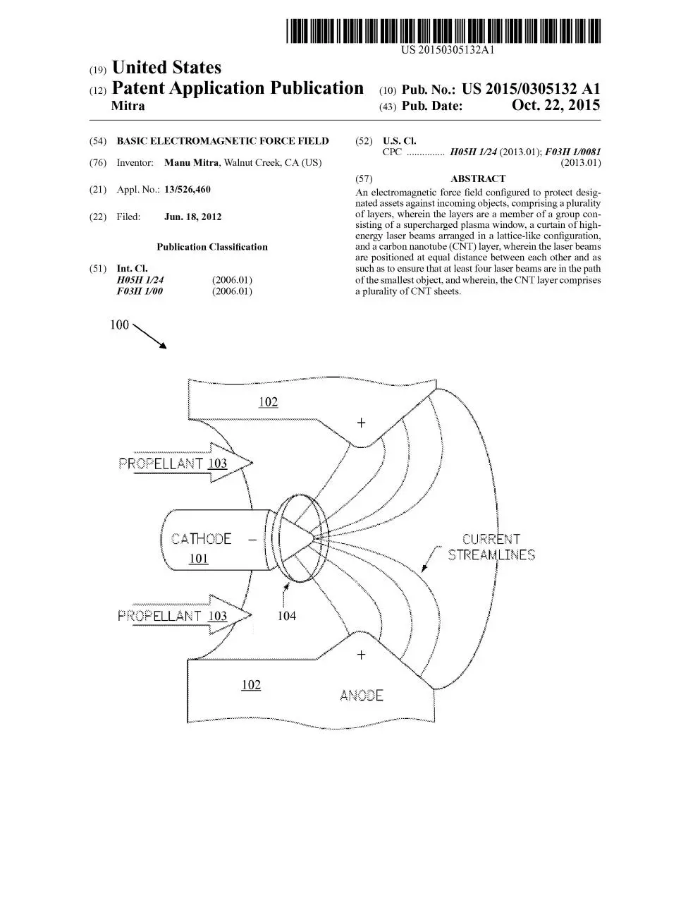
0022 FIG. 1 illustrates the working principle of a plasma
field generator 100. As shown, in the basic form, the plasma
field generator has two metal electrodes: a central rod-shaped
cathode 101, and a cylindrical anode 102 (half shown only)
that surrounds the cathode 101. When a high-current electric
arc is struck between the anode 101 and cathode 101, as the
cathode 101 heats up, it emits electrons, which collide with
and ionize a propellant gas 103 to create plasma. A magnetic
field 104 is created by the electric current returning to the
power supply (not shown) through the cathode 101, just like
the magnetic field that is created when electrical current trav
els through a wire. The self-induced magnetic field 104 inter
acts with the electric current flowing from the anode to the
cathode (through plasma) to produce an electromagnetic
US 2015/0305132 A1
(Lorentz) force that pushes the plasma out of the device/
generator, thus, creating a plasma field. A magnet coil (not
shown), external to the anode, may also be used to provide
additional magnetic field to help stabilize and accelerate the
plasma discharge.
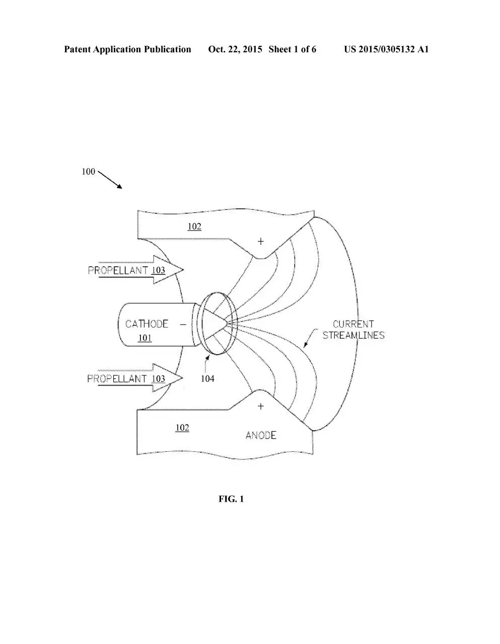
0023 FIG. 2 illustrates an exemplary construction of an
improved, self-field, coaxial, plasma field generator 200.
0024. As shown in FIG. 2, this plasma generator utilizes a
hollow cylindrical anode 202, which forms a discharge cham
ber 212, and a hollow or a multichannel hollow (for improved
efficiency) cathode 201. As shown, the cylindrical anode 202
is open at one end (this is the end through which plasma is
pushed out, thus, creating a plasma field), and closed at the
other end with an insulator backplate 214, to prevent the
plasma from exiting through that end. There are two electro
magnets (not shown) inside the anode, that establish a direct
current magnetic field which is primarily parallel to the
thruster axis passing through the discharge chamber. A small
angle of divergence between the axial and radial directions
exists in the magnetic flux density.
0025 All outside surfaces of the generator are coated with
aluminum oxide to insulate them from plasma.
0026. As shown a high voltage power source 216, powers
the generator.
0027. The plasma window may fill a volume of space with
plasma which is confined by a magnetic shield. Plasma win
dows are generally heated to very high temperatures, but the
temperature may vary depending upon the application.
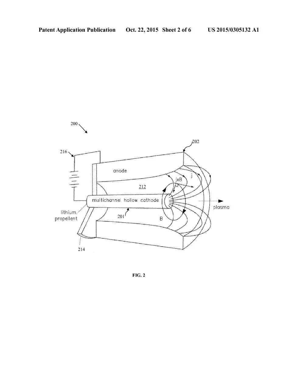
0028 FIG.3 depicts a schematic view of flow of plasma
using Lorentz accelerator principle. As shown, from the cur
rent source 316, current flows into the nearer rail322, through
the plasma 330 and then back, through the far rail 324, to the
current source 316. It is known that current through conduc
tors causes magnetic field. Since the plasma 330 now carries
the current, it has the same accelerating force as the magnetic
field. This results in the plasma 330 being accelerated out
through the end 334 of the channel 332 formed by the two
electrodes 322 and 324, thus, providing a plasma force.
0029 FIG. 4 depicts the schematic diagram of a gas dis
charge laser 400. As mentioned earlier, the second layer of the
electromagnetic force field disclosed herein is a laser curtain.
As shown, a gas discharge laser 400 includes a housing 441,
with a 100% reflecting spherical mirror 450 at each end, and
enclosing spaced-apart electrodes, 442 and 443, and a lasing
gas (e.g., CO2, N. He) filling the cavity/space 444 available
inside housing 441, including between electrodes 442 and
443. A laser resonator 445 extends between the spaced-apart
electrodes 442 and 443. An RF power supply 446 provides RF
power for creating a discharge in the lasing gas, causing laser
radiation to be delivered by the laser resonator 445. The
power of the output radiation is directly dependent on the RF
power provided to the electrodes 442 and 443, and inversely
dependent of the temperature of the gas discharge.
0030. As mentioned earlier, a lasing gas such as CO2 can
be adopted to produce the laser curtain. The laser may employ
a pumping scheme which serves to excite the lasing gas
uniformly, and thus, enhancing the transfer of pump energy
into laser energy. In practice, a number of pumping schemes
may be used Such as, a flash bulb, or electronic pumping.
Pumping with a coherent source like a laser allows picking a
specific energy state transition to excite, which allows a finer
control over the lasing wavelengths that the laser will operate
in. For example, at 10.6 um, laser is totally invisible to the
human eye.
Oct. 22, 2015
0031 FIG. 5 depicts an exemplary second layer, laser
curtain 500, of the electromagnetic force field. As shown,
there are multiple beams of laser 501 in the layer, to form a
laser curtain 500. The laser curtain 500 may be formed by
using many laser beams 501 simultaneously. Various laser
frequencies can be used to improve laser curtain's efficiency
(to vaporize an incoming projectile for example). If config
ured to have enough intensity, whenever an object passes
through the laser curtain, the laser curtain heats up the object
and vaporizes the metals in it (or other materials). Although
not shown in FIG. 5, it is preferred that the laser beams 501 be
equidistant in both directions of the laser curtain (e.g., verti
cally and horizontally) to prevent the creation of loopholes
(e.g., 575) that would facilitate the passage through the laser
curtain of an incoming object. In addition, the equal distance
between the laser beams should be smaller than the expected
size of the Smallest incoming objects. Furthermore, for
increased efficiency of the laser curtain, it is preferred to have
minimum four beams (i.e., two beams in each of the two
directions (e.g., two vertical beams and two horizontal
beams)) in the path of an incoming object. As such, when
selecting the distance between the beams, this aspect has to be
considered as well.
0032 FIG. 6 depicts the molecular dynamics model 600 of
a carbon nanotube layer subjected to ballistic impact. 601-a
depicts the initial model, before impact. 601-b depicts a
deformed model at its maximum energy absorption. As stated
earlier, the third layer of the electromagnetic force field is
made of carbon nanotubes (CNT). Carbon nanotubes are
hollow cylinders made of carbon atoms that are one-billionth
of a meter. For increased strength of the carbon nanotube
layer, double walled carbon nanotubes may be used. In addi
tion, for increased strength of the third layer of the electro
magnetic force field, it is preferred that more than one CNT
sheet is used (e.g., two or three CNT sheets). The CNT sheets
may be positioned next to each other or spaced apart, to create
the third layer of the electromagnetic force field.
0033. When a projectile 660-a, 660-b strikes carbon nano
tubes (see 601-b and 660-b), the fibers of these materials
absorb and disperse the impact energy to successive layers of
CNT to prevent the projectile 660-b from penetrating this
third layer of the electromagnetic force field. The speed of the
projectile 660-b decreases due to its energy loss when impact
ing a CNT (the energy is absorbed by the CNT), and becomes
Zero when the CNT absorbs and dissipates all the energy of
the projectile.
0034 FIG. 7 depicts schematically the combination of the
three layers (i.e., plasma field, laser curtain, and carbon nano
tubes shield) that form the electromagnetic force field as
described above. It should be understood that two layers may
be enough to create an equivalent electromagnetic force field
usable for similar applications as the three-layer field. For
example, if the plasma layer is doubled strength-wise, the
third layer of CNT may be eliminated as the second laser layer
may be enough to vaporize the fewer objects or portions of
objects that may escape the double-in-strength first plasma
layer. Similarly, the laser layer may be eliminated, as the CNT
layer may be enough to repel the fewer objects or portions of
objects that may escape the double-in-strength first plasma
layer.
0035. It should also be understood that more than three
layers may be used, as such configuration may increase the
strength of the force field. For example, a four-layer force
US 2015/0305132 A1
field may be used arranged in the following order: plasma
layer—laser layer plasma layer—CNT layer (last layer).
0036. The electromagnetic force field disclosed herein
may be used to protect designated assets (e.g., military assets
Such as a tank) against incoming objects such as projectile
weapons.
0037. It may be advantageous to set forth definitions of
certain words and phrases used in this patent document. The
term “couple' and its derivatives refer to any director indirect
communication between two or more elements, whether or
not those elements are in physical contact with one another.
The terms “include’ and “comprise.” as well as derivatives
thereof, mean inclusion without limitation. The term 'or' is
inclusive, meaning and/or. The phrases “associated with and
“associated therewith as well as derivatives thereof, may
mean to include, be included within, interconnect with, con
tain, be contained within, connect to or with, couple to or
with, be communicable with, cooperate with, interleave, jux
tapose, be proximate to, be bound to or with, have, have a
property of, or the like.
0038 Although specific embodiments have been illus
trated and described herein for the purpose of disclosing the
preferred embodiments, someone of ordinary skills in the art
will easily detect alternate embodiments and/or equivalent
variations, which may be capable of achieving the same
results, and which may be substituted for the specific embodi
ments illustrated and described herein without departing from
the scope of the invention. Therefore, the scope of this appli
cation is intended to cover alternate embodiments and/or
equivalent variations of the specific embodiments illustrated
and/or described herein. Hence, the scope of the invention is
defined by the accompanying claims and their equivalents.
Furthermore, each and every claim is incorporated as further
disclosure into the specification and the claims are embodi
ment(s) of the invention.
What is claimed is:
1. An electromagnetic force field configured to protect
designated assets against incoming objects, comprising a plu
rality of layers, wherein the layers are a member of a group
consisting of a Supercharged plasma window, a curtain of
high-energy laser beams arranged in a lattice-like configura
Oct. 22, 2015
tion, and a carbon nanotube (CNT) layer, wherein the laser
beams are positioned at equal distance between each other
and as such as to ensure that at least four laser beams are in the
path of the smallest object, and wherein, the CNT layer com
prises a plurality of CNT sheets.
2. The electromagnetic force field of claim 1, wherein the
protection includes heating the objects to high temperatures
Such that the objects vaporize.
3. The electromagnetic force field of claim 1, wherein the
protection includes repelling objects by the use of the CNT
layer.
4. The electromagnetic force field of claim 1, wherein the
incoming objects are projectile weapons.
5. The electromagnetic force field of claim 1, wherein the
Supercharged plasma window is obtained by generating the
plasma using a coaxial plasma field generator and by confin
ing the plasma by a magnetic shield.
6. The electromagnetic force field of claim 5, wherein the
high-energy laser beams are obtained using a gas discharge
laser comprising a housing with a reflecting spherical mirror
at each end, two spaced-apart electrodes, a lasing gas, and a
laser resonator.
7. The electromagnetic force field of claim 6, wherein the
force field comprises only two layers, a Supercharged plasma
window as the first layer and a curtain of high-energy laser
beams as the second layer.
8. The electromagnetic force field of claim 1, wherein the
force field comprises only two layers, a Supercharged plasma
window as the first layer and a plurality of CNT sheets as the
second layer.
9. The electromagnetic force field of claim 6, wherein the
force field comprises only three layers, a Supercharged
plasma window as the first layer, a curtain of high-energy
laser beams as the second layer and a plurality of CNT sheets
as the third layer.
10. The electromagnetic force field of claim 6, wherein the
force field comprises only four layers, a Supercharged plasma
window for both, the first and the third layer, a curtain of
high-energy laser beams as the second layer and a plurality of
CNT sheets as the fourth layer.
k
k
k
k
k
Download 02. Basic Electromagnetic Force Field (US20150305132A1)
02. Basic Electromagnetic Force Field (US20150305132A1).pdf (PDF, 604.31 KB)
Download PDF
Share this file on social networks
Link to this page
Permanent link
Use the permanent link to the download page to share your document on Facebook, Twitter, LinkedIn, or directly with a contact by e-Mail, Messenger, Whatsapp, Line..
Short link
Use the short link to share your document on Twitter or by text message (SMS)
HTML Code
Copy the following HTML code to share your document on a Website or Blog
QR Code to this page

This file has been shared publicly by a user of PDF Archive.
Document ID: 0001888992.