FinalReport FairingWell (PDF)
File information
Title: Microsoft Word - FinalReport_FairingWell.docx.docx
This PDF 1.3 document has been generated by Word / Mac OS X 10.10.5 Quartz PDFContext, and has been sent on pdf-archive.com on 22/10/2018 at 03:22, from IP address 69.27.x.x.
The current document download page has been viewed 299 times.
File size: 6.16 MB (12 pages).
Privacy: public file


File preview
ENGR 110: Perspectives in Assistive Technology
Aesthetic Leg Brace Fairing Project
Final Report
Team Name: Fairing Well
Team Members: Jess Moss, Anna Olson, Lisa Su
Winter 2016
Pictured: Anna Olson (ME ’16), Jess Moss (ME ’16), Lisa Su (ME ’16), Max Conserva
ABSTRACT
Our team, Fairing Well, aims to design and build an aesthetic leg brace fairing for Max Conserva,
an athlete who requires orthotic leg braces on his right leg. Although the orthotics restore
function to the leg, they serve no aesthetic purpose. As a result, the leg deformity is still visually
apparent. By adding an external fairing, we hope to mask the difference in the size and shape of
the legs. In approaching this project, we first sought out products currently on the market that
serve similar functions—namely, prosthetic fairings—for design inspiration. We then moved to
creating low fidelity prototypes using cardboard and splinting material to identify our desired
general shape and scale. Next, we created a thermoformed PETG prototype fairing off a
positive mold that we constructed from laser-cut duron cross sections and Bondo. We
continued to iterate on the mold design and created successive thermoformed pieces until we
were satisfied with the shape. We ultimately manufactured a final fairing shell out of ⅛’’ black
opaque ABS plastic. Lastly, we used a Velcro to invisibly and securely attach the fairing to the
leg brace.
INTRODUCTION
In this project, our team aims to create
an aesthetic leg brace fairing for Max
Conserva. Max, pictured in Figure 1,
experienced massive trauma to his right
leg at a young age. As a result, his leg is
significantly disfigured from both the
accident and growing deformities over
the years. The entire limb is intact, but
has a smaller girth as well as abnormal
contours, angle, and rotation compared
to his other limb. His orthotics, devices
Figure 1. Max Conserva: engineer, athlete, adaptive
athletics advocate, and recipient of finished product.
that function to support and align the orthopedic injury, make a significant functional impact
and allow Max to pursue his current profession as a Crossfit trainer. Although Max is not
significantly functionally impaired by his injury, the aesthetic effect is ever-present. With our
aesthetic leg brace fairing, we hope to mitigate the aesthetic differences in his legs by attaching a
streamlined and sleek external structure (the external fairing) to the leg brace.
Currently, no such aesthetic add-on product exists on the market for orthotics. Some human
limb fairings for prosthetics exist, most notably designed by companies such as Bespoke
Innovations1 and UNYQ2. However, the issue of creating a fairing for a limb orthotic is
significantly different than creating a fairing for a prosthetic, since the orthotic must fit around
an existent limb and all of its functional hardware. It is difficult to quantify the population
experiencing limb disfigurement and requiring prosthetic or orthotic devices; this is due in part
to the unique nature of prosthetics and orthotics where each patient has a unique disfigurement
and needs3. A current rule-of-thumb estimate places the number of orthotic patients at ten
times the number of amputees (a population presumed to require prosthetics), suggesting a
sizable orthotics market compared to that for prosthetics. Furthermore, due to the unique
nature of many limb disfigurements, physical differences between humans, and different
lifestyle requirements, well-designed orthotics require a unique solution for each patient. As a
result, most work on orthotics and limb disfigurement focuses first on increasing the
functionality of the limb and does not address aesthetic elements. However, the psychological
impact of visual appearance cannot be overlooked. Visual appearance can often affect a
patient’s confidence and willingness to embrace and push the functionality of their limb. This in
turn has a great impact on a person’s confidence and self-image. We hope to create a solution
that perfectly fits Max’s deformity and leg braces to create a truly customized aesthetic fairing.
OBJECTIVES
Our most important objective for this project is to physically produce an external covering for
the limb that “looks great.” Visually, Max is hoping for a device that allows his right leg to
appear normal in shape and pattern. More than color or texture, the general shape of the
humanoid pattern and any deviations is what draws the eye, from up close as well as from afar.
Without the fairing, it’s visually obvious that Max’s right leg is not only smaller in girth than the
left, but also curves in medially towards the center of the body. We hope for the fairing to
visually fill in the space that the right leg would ordinarily take up. Lastly, the fairing should be
simple to wear and detach at will.
Outside of the aesthetic requirement, the fairing needs to fulfill a number of other goals in
order to serve a useful function. First, Max noted the fairing should be relatively easy to put on
and take off. This requirement pointed us towards a fastener mechanism that does not involve
manipulating difficult to reach parts and does not require additional tools. Similarly, we didn’t
want the fairing to come with extraneous attachment hardware; we wanted it to function
independently as a detachable wearable piece for the orthotic brace.
In addition, the fairing must not interfere with the function of Max’s limb. The fairing cannot
make the limb uncomfortable or limit its range of motion. We focused on two main properties:
breathability and bulk. Since the fairing would be likely a solid external piece, it cannot cut off
air circulation to the limb in such a way that the limb would become uncomfortably hot. As a
result, we had to be careful in our design to not create a fairing that depends on hugging the
existing limb in any way to stay on. In terms of bulk, we do not want the fairing to affect how
Max walks and moves. We needed to design the fairing to stay out of the way of existing
functional hardware and not interfere with his shoes or other parts of his legs during any
activity. Especially considering Max’s profession as a Crossfit trainer, these requirements are
essential to the aesthetic functionality of the fairing. However, the fairing itself does not need to
hold any weight or provide any structural support for the limb or underlying orthotics.
We have not only created a custom fairing that meets all of Max’s initial goals but also a
documented process for creating more. Our team and Max agree that a well-defined and
repeatable process for creating such a fairing from beginning to end for any unique
disfigurement was an ideal reach goal that our team definitively reached.
DESIGN CRITERIA
To get a better idea of what our final product might look like, we looked to existing limb
fairings that are on the market. The products created by companies such as Bespoke
Innovations, UNYQ, and altLimbPro5 are all fairings for prosthetics, however, these products
provided us a good idea of what is out there. These products mostly used plastics with
perforations, which likely were both aesthetic and functional for breathability. In addition, we
noticed that these products predominantly mimicked the natural limb most in general shape and
size but made no attempt to mimic the color or texture. Unlike the prosthetic fairings, we will
need to interface with an existing limb and the existing functional hardware of the leg braces.
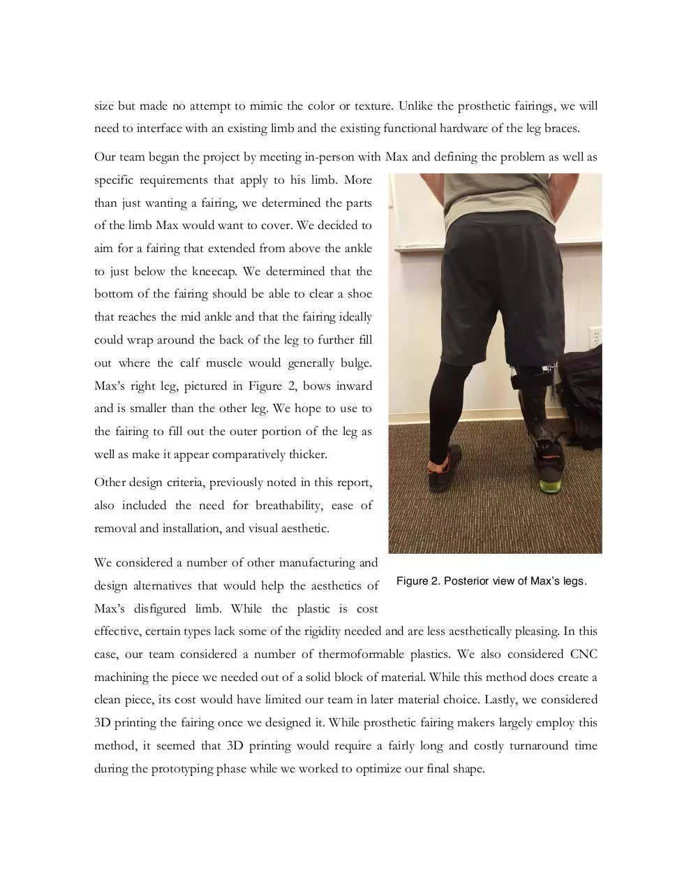
Our team began the project by meeting in-person with Max and defining the problem as well as
specific requirements that apply to his limb. More
than just wanting a fairing, we determined the parts
of the limb Max would want to cover. We decided to
aim for a fairing that extended from above the ankle
to just below the kneecap. We determined that the
bottom of the fairing should be able to clear a shoe
that reaches the mid ankle and that the fairing ideally
could wrap around the back of the leg to further fill
out where the calf muscle would generally bulge.
Max’s right leg, pictured in Figure 2, bows inward
and is smaller than the other leg. We hope to use to
the fairing to fill out the outer portion of the leg as
well as make it appear comparatively thicker.
Other design criteria, previously noted in this report,
also included the need for breathability, ease of
removal and installation, and visual aesthetic.
We considered a number of other manufacturing and
design alternatives that would help the aesthetics of
Figure 2. Posterior view of Max’s legs.
Max’s disfigured limb. While the plastic is cost
effective, certain types lack some of the rigidity needed and are less aesthetically pleasing. In this
case, our team considered a number of thermoformable plastics. We also considered CNC
machining the piece we needed out of a solid block of material. While this method does create a
clean piece, its cost would have limited our team in later material choice. Lastly, we considered
3D printing the fairing once we designed it. While prosthetic fairing makers largely employ this
method, it seemed that 3D printing would require a fairly long and costly turnaround time
during the prototyping phase while we worked to optimize our final shape.
METHODS
To begin our prototyping process, our team started by
independently sketching (Figure 3) overviews of the
final
product
and
brainstorming
manufacturing
processes. We discussed these notes with Max and in
the same meeting created a low fidelity prototype to
get the general size and shape fairing. The low fidelity
prototype (Figure 4) was created with cardboard that
was scored to give it a greater capacity to bend and
conform to the natural curves of Max’s leg. We placed
the cardboard against Max’s leg and sketched out
where we hoped for the fairing to start and end. We
also started to explore the benefits of embedding more
organic curves into the design of the fairing.
Figure 3. Preliminary brainstorming
sketches (Anna’s)
Moving forward with our prototyping
process, we sought to create a more
rigid and higher definition model of the
fairing. Using a SAM splint, which
consists of a pliable aluminum sheet
contained within two layers of foam, we
created a rigid prototype. At this point,
we
were
already
considering
manufacturability and realized that the
thermoformer would not be able to
manufacture a piece that goes more
than 180 degrees radially. Since the
original cardboard prototype spanned
about 270 degrees, we quickly realized
Figure 4. Scored cardboard prototype.
that we would need to split the fairing into
two. In making the SAM splint model, we also
iterated with different splitting patterns along
the long axis of the leg and settled with a split
on the lateral side of the leg (Figure 5).
Using our SAM splint rigid model, we took
careful measurements and recreated the fairing
we were hoping to manufacture as a surface in
SolidWorks (Figure 6). Using this SolidWorks
model, we decided to move forward with a
higher resolution manufacturing process. The
game plan was to create a positive plug mold,
pull
thermoformed
1/16’’
PETG
sheet
iterations on the mold, and edit the mold via
sanding or additive fillers until the shape was
just right. When the positive mold was
Figure 5. SAM splint prototype with lateral side split.
finalized, we would layup a fairing with a final
material, either carbon fiber or fiberglass. All
the while, we would be exploring different
fasteners that could interface with the existing
braces.
Originally, our hope was to fabricate the
positive plug out of modulan and CNC
machine the shape. However, the modulan
was prohibitively expensive (>$100) for a
Figure 6. SolidWorks models.
single block the size of a lower leg. Instead of a subtractive manufacturing technique on the
large modulan block, we decided upon an additive process. Using our CAD model, we took ¼’’
thick cross sections and laser cut the slices out of duron. We stacked and glued these cross
sections, then smoothed the ridges with Bondo (Figure 7).
Figure 7. The positive mold making process.
Using these molds, we vacuum formed our first clear PETG prototype fairing and set the
process to continue iterating until the general shape exactly matches Max’s leg’s needs We
edited the mold with sandpaper and Bondo until the shape was completely accurate to fit Max’s
leg through several iterations. We tested several thermoformable plastics until we decided upon
our final material—black ⅛’’ ABS.
After determining the final shape and fit of the fairing, our team approached fastening the
fairing rigidly to Max’s existing brace. After experimenting with a large variety of mechanical
fasteners, from Velcro and clips to
magnets and screws, our team found
that a flush fit with the existing brace
edge would give us the cleanest
aesthetic look. We also kept in mind
other design requirements we had
previously determined, such as a toolless, quick on-and-off process and
conferenced with Max to decide on a
solution that did not require any
permanent mounting or changes to his
functional brace.
Ultimately, our team used a Velcro
mounting system along the inside of
the fairing to fasten the brace. (Figure
8).
Figure 8. Velcro attachment.
The Velcro system was reliable and had the benefit of being able to incorporate a completely
invisible seam. Aesthetically, this was by far our best option and fit all of our previous design
requirements.
Our final prototype used the Velcro system described above and was bead-blasted for an
aesthetic black matte finish. As an extra touch, we incorporated Max’s personal logo for the
Good Leg Project into the design (Figure 9).
Figure 9. Final fairing with bead-blast finish and vinyl logo masking.
RESULTS
Ultimately, we were able to create a finished product that met the design specifications we
originally laid out (Figure 10). In particular, our brace was aesthetically pleasing, easy to attach,
and remained rigid attached to the current leg brace. In terms of aesthetics, through many
iterations, we were able to create an organic three dimensional shape that was able to mirror an
anatomical leg. Through the process of bead blasting, we were able to create a matte finish that
furthered the fairing’s appearance. For attachment methods, we found that Velcro was easy,
tool-less, and not visible while being worn.
Figure 10. Finished orthotic leg brace fairing worn by Max Conserva.
Luckily, our product was not structural. In terms of concerns, we only needed to ensure it did
not interfere with the current brace. Since our product method did not require any alterations to
the current leg brace, we found no safety issues. In terms of cost, our final product was
extremely affordable, costing only $26 in raw materials to manufacture. However, the
manufacturing process did require access to special tooling such as the thermoformer at the
Stanford PRL.
In addition, we were lucky to share this product with its intended user. Max was very pleased
with the overall shape and design of the fairing. He also shared a photo of it on social media
and reported that within hours someone had inquired about where they could acquire their own
orthotic fairing. In the future, Max expressed interest in exploring options of creating the fairing
out of a different material such as carbon fiber or fiberglass. For these future options, our
positive mold and original CAD model will provide a valuable starting location.
DISCUSSION
Moving forward with the project, our team would considering using the mold to create a high
fidelity negative mold and try more alternative final materials. Our team has discussed carbon
fiber or fiberglass layup as possible next-step materials.
Other extensions of the project include creating a greater wraparound angle for the fairing so
that it also covers and adds to the posterior side of the leg (calf). In addition, our team would
consider implementing a more permanent fastener system than Velcro. While Velcro offers a
highly functional solution, it lacks the satisfactory tactile and auditory feedback that a
mechanical fastener would upon successful installation.
Finally, our team would consider creating more thorough manufacturing documentation and
instruction in creating these custom fairings to make them more available to a general
population. Max has enough to continue the project for himself but the process is not yet fully
customizable.
NEXT STEPS
In continuing this project as a ME113 project, our team would focus on creating the carbon
fiber layer prototype. The major challenges would be sourcing materials and developing the
craftsmanship for aesthetically pleasing layups.
One possible timetable is shown below:
Week No.
Tasks/Deliverables
3
Explore negative mold fabrication options & considerations
4
First negative mold manufactured, fastener prototypes
5
First lay-up, evaluation, plans for revisions, evaluate fasteners
7
Implement changes, next iteration lay-up, finalize fasteners
9
Final iteration of lay-up, fastener system implemented
10
Final project due, finish project documentation
REFERENCES
1 Bespoke Innovations: http://www.bespokeinnovations.com
2 Unyq: http://www.unyq.com
3 Maurice A. LeBlank, M.S., C.P. “Patient Population And Other Estimates Of Prosthetics And
Orthotics In The U.S.A.” American Orthotic & Prosthetic Association (AOPA), n.d., Web. 17
Mar. 2016.
4 The Good Leg Project http://www.goodleg.org
5 AltLimbPro: The Alternative Limb Project http://www.thealternativelimbproject.com/
AKNOWLEDGEMENTS
Our team would like to thank Dave Jaffe, our course instructor, for his guidance throughout the
project, from project determination to prototyping to finalizing our design. We also would like
to thank the Stanford PRL TA’s for their experience and advice throughout the prototyping
process. Finally, we owe a huge thank you to Max for his expertise as well as his continued
involvement and feedback—our project’s success stems from Max’s enthusiasm and
engagement in addressing improvements to orthotic technologies.
Download FinalReport FairingWell
FinalReport_FairingWell.pdf (PDF, 6.16 MB)
Download PDF
Share this file on social networks
Link to this page
Permanent link
Use the permanent link to the download page to share your document on Facebook, Twitter, LinkedIn, or directly with a contact by e-Mail, Messenger, Whatsapp, Line..
Short link
Use the short link to share your document on Twitter or by text message (SMS)
HTML Code
Copy the following HTML code to share your document on a Website or Blog
QR Code to this page

This file has been shared publicly by a user of PDF Archive.
Document ID: 0001899694.