pm3010gsnl 140 v1 user manual (PDF)
File information
Title: pm3010gsnl-140-v1-visible-lcd-poe-switch-user-manual
Author: unipoe
This PDF 1.7 document has been generated by WPS Office / , and has been sent on pdf-archive.com on 07/11/2018 at 03:41, from IP address 36.228.x.x.
The current document download page has been viewed 398 times.
File size: 1.51 MB (11 pages).
Privacy: public file


File preview
PM3010GSNL
8+2 全千兆可视 PoE 交换机
8+2 Gigabit PoE Switch
Package Contents
Check the following contents of your package:
PoE Switch x 1
User Guide x1
Power Cord x1
Accessories(Rack Mount Accessory Kit*2 ,Rubber Feet*4, screw*8)
If any part is lost and damaged, please contact your local agent immediately.
Introduction
PM3010GSNL contains 10 RJ45 ports and 1~8 support PoE functions. The PoE ports can automatically detect and supply
power to IEEE802.3af/at compliant Powered Devices (PD). The electrical power and data transmission on the same cable
can expand your network to the places where no power lines or outlets, where you can install devices such as APs, IP
cameras, or IP phones etc.
The LCD not only can display the PoE work status, accurate judgment port of load, can also help customer and engineer
timely discover and solve the network failure, improve work efficiency and quality. The PM3010GSNL has VLAN function
that improve the network environment and reduces network maintenance costs.
Hardware Description
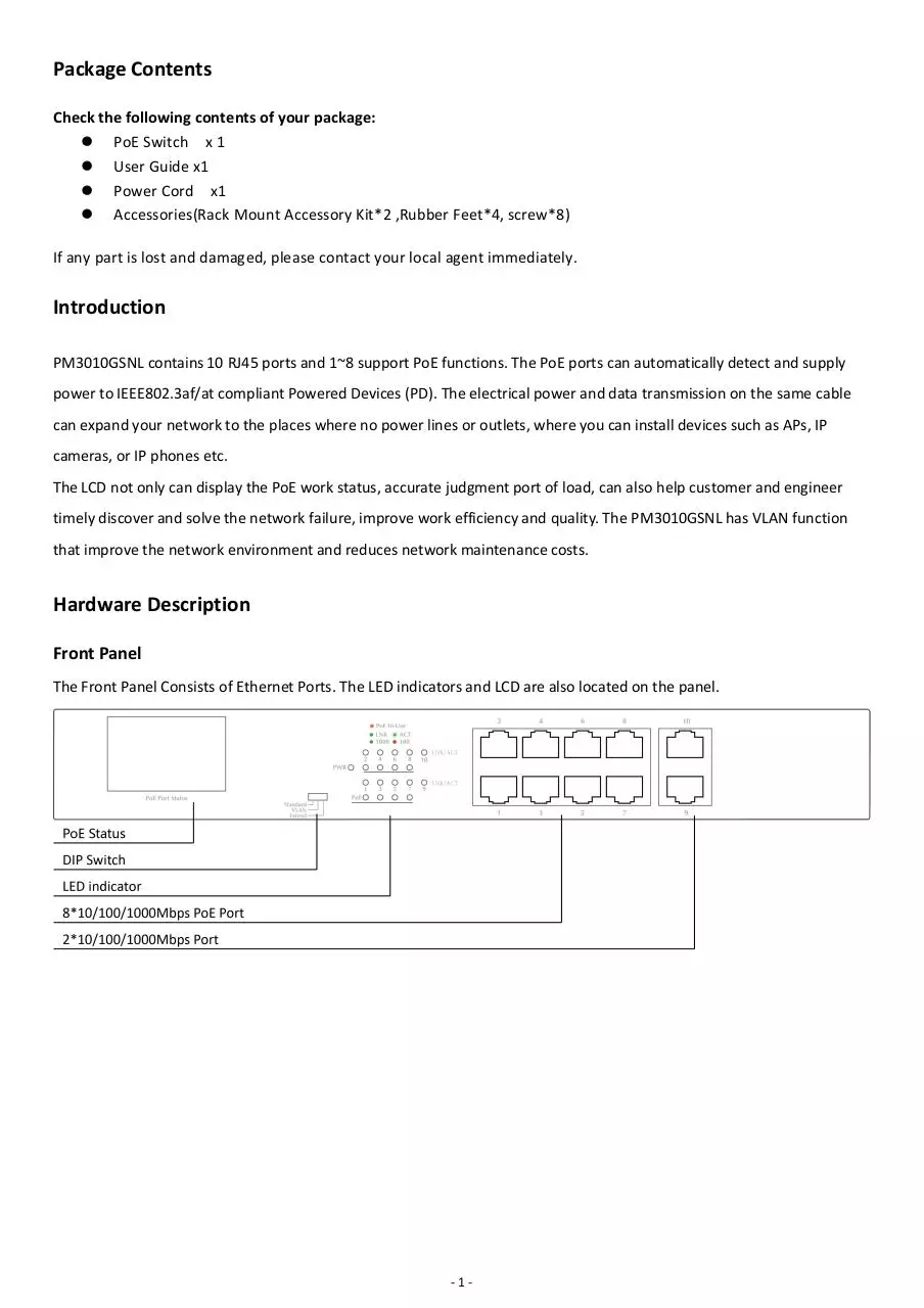
Front Panel
The Front Panel Consists of Ethernet Ports. The LED indicators and LCD are also located on the panel.
-1-
PoE Status
The PoE Switch is with the function of the LCD display and PoE. The LCD can display the working condition of PoE port not
only, still can accurately show the state of each port, such as: Output power, Overload, Short circuit, Light load, Low voltage,
Over voltage,High temperature, and so on...
DIP Switch
The DIP switch located on the left panel.
Standard: the factory default mode, can normal communication between port 1~10.
VLAN: 1-8 port can be isolated each other but 1-8 port can connect to 9/10 port after open VLAN to stop broadcast storm
to increase forwarding rate of frame.
Extend: Up to 250m PoE distance allows you to expand you network via Ethernet cable to where there is no power line or
outlet but where you want to fix device such as IP Cameras.
LED indicator
LED
Color
Function
PWR
Green
Off: No Power supply.
Light: Indicates the switch has power.
Red
Off: No device is connected to the corresponding port.
Light: Indicates the link through that port is successfully
established at 10/100Mbps.
Blink: Indicates that the Switch is actively sending or
receiving data over that port.
Green
Off: No device is connected to the corresponding port.
Light: Indicates the link through that port is successfully
established at 1000Mbps.
Blink: Indicates that the Switch is actively sending or
receiving data over that port.
Orange
Off: No PoE powered device (PD) connected.
Light: There is a PoE PD connected to be port, which
supply power successfully.
Blink: Indicates port abnormal power supply.
LNK/ACT
PoE
-2-
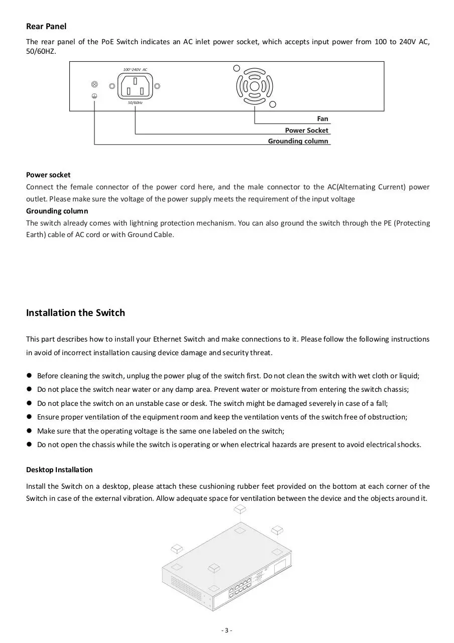
Rear Panel
The rear panel of the PoE Switch indicates an AC inlet power socket, which accepts input power from 100 to 240V AC,
50/60HZ.
Power socket
Connect the female connector of the power cord here, and the male connector to the AC(Alternating Current) power
outlet. Please make sure the voltage of the power supply meets the requirement of the input voltage
Grounding column
The switch already comes with lightning protection mechanism. You can also ground the switch through the PE (Protecting
Earth) cable of AC cord or with Ground Cable.
Installation the Switch
This part describes how to install your Ethernet Switch and make connections to it. Please follow the following instructions
in avoid of incorrect installation causing device damage and security threat.
Before cleaning the switch, unplug the power plug of the switch first. Do not clean the switch with wet cloth or liquid;
Do not place the switch near water or any damp area. Prevent water or moisture from entering the switch chassis;
Do not place the switch on an unstable case or desk. The switch might be damaged severely in case of a fall;
Ensure proper ventilation of the equipment room and keep the ventilation vents of the switch free of obstruction;
Make sure that the operating voltage is the same one labeled on the switch;
Do not open the chassis while the switch is operating or when electrical hazards are present to avoid electrical shocks.
Desktop Installation
Install the Switch on a desktop, please attach these cushioning rubber feet provided on the bottom at each corner of the
Switch in case of the external vibration. Allow adequate space for ventilation between the device and the objects around it.
-3-
Rack-mountable Installation
The switch is rack-mountable and can be installed on an EIA-19 inch equipment rack. To do this, first, please install the
mounting brackets on the switch’s side panels (one on each side), secure them with the included screws, and then use the
screws provided with the equipment rack to mount the switch on the 19 inch rack.
Turn on the switch
Please connect the AC power cord into the rear of the switch and to an electrical outlet (preferably one that is grounded ).
When the switch is power on, the LED indicators flash momentarily for one second, which represents a resetting of the
system.The Power LED indicator turns on green.
Note: Please confirm the voltage is correct before power on, otherwise the switch will be damaged.
(The power input is:100V-240Vac, 50/60Hz.)
-4-
Specifications
Model
Standard
Network Media
MAC Address Table
Transfer mode
Frame Forward Rate
Switching Capacity
Dimensions (L*W*H)
Fan Quantity
Power Input
PoE Port
PoE Power on RJ45
PoE Power Output
PoE Power Budget
Temperature
Humidity
PM3010GSNL
IEEE802.3, IEEE802.3u, IEEE802.3ab, IEEE802.3az, IEEE802.3x
IEEE802.3af, IEEE802.3at
10BASE-T: UTP category 3,4,5 cable (≤100m)
100BASE-TX: UTP category 5 cable (≤100m)
1000BASE-T: UTP category 5e cable (≤100m)
8K, Auto-learning, Auto-aging
Store-and-Forward
10Base-T: 14881pps/Port
100Base-TX: 148810pps/Port
1000Base-T/X: 1488095pps/Port
20G
280 *179 *44.5 mm
1
AC: 100~240V, 50/60Hz
Port1~8
Mode A 1/2(-),3/6(+)
Voltage: 55V DC Power: 32W(Max)
120W
Operating Temperature: 0°C ~ 40 °C (32 °F ~104°F )
Storage Temperature: -40 °C ~ 70 °C (-40 °F ~158°F )
Operating Humidity: 10% ~ 90% non-condensing
Storage Humidity: 5% ~ 90% non-condensing
-5-
包装清单
小心打开包装盒,包装盒内应有以下物件:
PoE 交换机 . . . . . . . . . . . . . . . . . . . . . . . . . . . . . . . . . .一台
用户手册 . . . . . . . . . . . . . . . . . . . . . . . . . . . . . . . . . . . .一本
电源线 . . . . . . . . . . . . . . . . . . . . . . . . . . . . . . . . . . . . . 一根
安装附件(挂钩*2、脚垫*4、螺丝*8)
如果发现有物件损坏或者短缺的情况,请及时和当地经销商联系。
产品简介
PM3010GSNL 具有 10 个千兆自适应 RJ45 端口。每个 RJ45 端口均支持 MDI/MDIX 自动翻转和线速转发功能。
其中 1~8 端口有 PoE 供电功能,支持 IEEE802.3af/at 标准,可作为以太网供电设备,能自动检测识别符合标准
的受电设备,并通过网线为其供电。
桌面壳体设计,同时可上机架,即插即用,无需管理。具有一键 VLAN 功能,用户可根据应用环境不同选择开启
或关闭 VLAN 功能,提升网络安全及抑制网络风暴。LCD 能显示 PoE 工作状态,对端口工作情况及负载情况进
行精确判断,以帮助客户及布线工程师及时发现和解决问题,排除网络故障,提高工作效率和工程质量。
外观描述
前面板
下列 PoE 交换机前面板示意图:
-6-
PoE 端口状态
LCD 屏能显示 PoE 端口的工作状况,对每个端口的输出功率、过载、短路、轻载、低压、过压、芯片过温等状态
作出精确显示,让您对 PoE 供电情况“芯”中有数。
VLAN 开关
Default:出厂默认模式,此模式下相当于一台普通的千兆PoE 交换机,端口 1~10 之间能正常通信。
VLAN: VLAN 隔离模式将交换机的端口 1~8 与端口 9/10 分别划分为一个单独的VLAN。端口 1~8 只能与9
和10进行通信。端口 1~8 之间不能之间通信,保障网络的安全。此模式下请将 9/10 接到中心交换设
备。
Extend:250米超长距离传输,可解决网络监控工程中需要远距离传输的问题,可替代光纤和网络延长器,解决超
远端取电难的问题, 降低工程布线成本。
LED 指示灯
指示灯
颜色
PWR
绿色
描述
灭: 交换机未通电
常亮:交换机已通电
灭: 没有连接网络设备
红色
常亮:连接了10/100M网络设备
闪烁:正在传输数据
LNK/ACT
灭: 没有连接网络设备
绿色
常亮:连接了1000M网络设备
闪烁:正在传输数据
灭: PoE端口没有供电
PoE
橙色
常亮:PoE端口正在供电
闪烁:PoE端口供电异常
-7-
后面板
PoE 交换机的后面板示意图: 交流电源接口,电源输入范围为 100-240V AC, 50/60HZ。防雷接地柱和风扇。
AC 电源接口
这是一个三相电源插座,把电源线阴性插头接到这个接口上,阳性插头接到交流电源上。
防雷接地柱
位于电源接口左侧,请使用导线接地,以防雷击。
安装设备
注意事项
为避免使用不当造成设备损坏及对人身的伤害,请遵从以下的注意事项:
在清洁交换机前,应先将交换机电源插头拔出。不要用湿润的布料擦拭交换机,不可用液体清洗交换机;
请不要将交换机放在水边或潮湿的地方,并防止水或湿气进入交换机机壳;
请不要将交换机放在不稳定的箱子或桌子上,万一跌落,会对交换机造成严重损害;
应保持室内通风良好并保持交换机通气孔畅通;
交换机要在正确的电压下才能正常工作,请确认工作电压同交换机所标示的电压相符;
为减少受电击的危险,在交换机工作时不要打开外壳,即使在不带电的情况下,也不要随意打开交换机机壳。
桌面安装
将交换机的底部朝上放置于足够大且稳定的桌面上;
撕掉随机附带的脚垫表面的粘贴纸,将脚垫粘贴到交换机机壳底部的凹槽内以防外部振动;
小心将交换机正置,放在工作台上。
-8-
机架式安装
检查 EIA-19inch 机柜的接地与稳定性,首先,用螺钉将安装挂耳固定在交换机前面板两侧将交换机放置在机柜的
一个托架上,沿机柜导槽移动交换机至合适位置,然后,用螺钉将安装挂耳固定在机柜两端的固定导槽上,确保交
换机稳定地安装在机柜槽位的托架上。设备的挂耳并不用来承重,它只起固定作用。安装设备于机柜时,设备机箱
的下边要有托架(固定在机柜上)来支撑设备。
开启交换机
接上电源线,插上插头,接通电源。开机以后,交换机将自动进行初始化,所有的端口指示灯全亮后熄灭,表示系
统复位成功。电源 LED 指示灯一直常亮。
注意:上电前请确认电压是否正确,否则将损坏设备。(电源输入范围 100-240V AC 50/60Hz)。
-9-
技术规格
PM3010GSNL
产品名
标准
标准
IEEE802.3、IEEE802.3u、IEEE802.3ab、IEEE802.3az、IEEE802.3x
IEEE802.3af、IEEE802.3at
10BASE-T:Cat 3、4、5 非屏蔽类双绞线(≤100m)
网络介质
100BASE-TX:Cat 5 及以上非屏蔽类双绞 线(≤100m)
1000BASE-T:Cat 5e 及以上非屏蔽类双绞线(≤100m)
MAC 地址表
8K,自动学习,自动更新
传输模式
存储转发
10Base-T:
包转发速率
14881pps/端口
100Base-TX: 148810pps/端口
1000Base-T/X: 1488095pps/端口
背板带宽
20G
尺寸(长*宽*高)
280*179*44.5mm
风扇数量
1
电源输入
AC: 100-240V, 50/60Hz
PoE 端口
Port1~Port8
PoE 供电线对
Mode A
PoE 端口输出
电压:55V DC
PoE 总功率
120W
工作温度
0°C ~ 40 °C
存储温度
-40 °C ~ 70 °C
工作湿度
10% ~ 90% 无凝结
存储湿度
5% ~ 90% 无凝结
1/2(-),3/6(+)
功率:32W(最大)
- 10 -
Download pm3010gsnl-140-v1-user-manual
pm3010gsnl-140-v1-user-manual.pdf (PDF, 1.51 MB)
Download PDF
Share this file on social networks
Link to this page
Permanent link
Use the permanent link to the download page to share your document on Facebook, Twitter, LinkedIn, or directly with a contact by e-Mail, Messenger, Whatsapp, Line..
Short link
Use the short link to share your document on Twitter or by text message (SMS)
HTML Code
Copy the following HTML code to share your document on a Website or Blog
QR Code to this page

This file has been shared publicly by a user of PDF Archive.
Document ID: 0001900311.