YM3812 V3 Build Guide Rev 1 3 (PDF)
File information
This PDF 1.4 document has been generated by Writer / LibreOffice 4.2, and has been sent on pdf-archive.com on 10/02/2019 at 13:34, from IP address 73.179.x.x.
The current document download page has been viewed 901 times.
File size: 3.83 MB (19 pages).
Privacy: public file
File preview
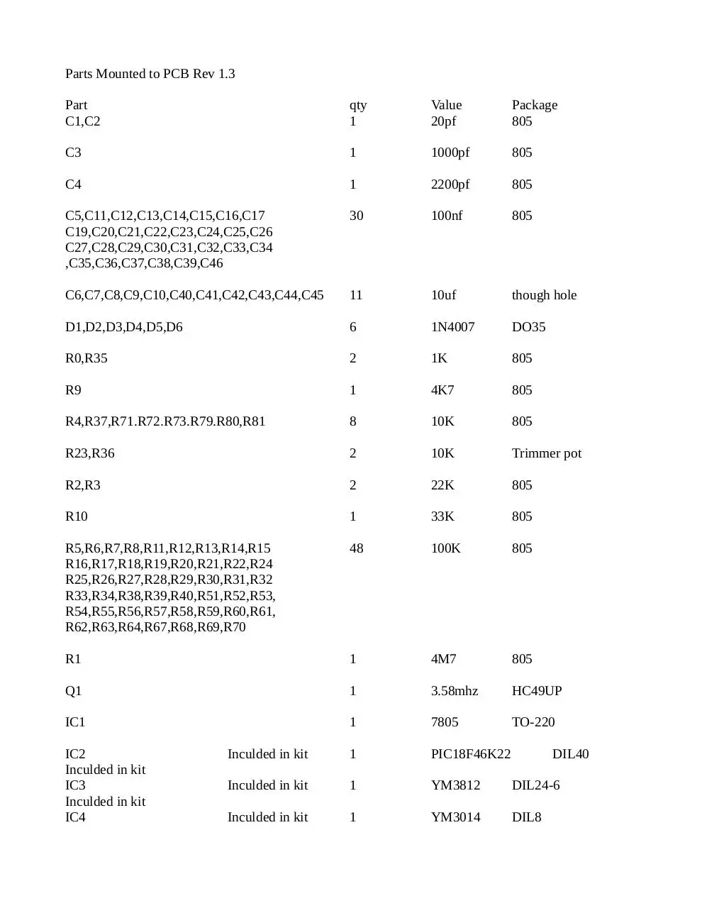
Parts Mounted to PCB Rev 1.3
Part
C1,C2
qty
1
Value
20pf
Package
805
C3
1
1000pf
805
C4
1
2200pf
805
C5,C11,C12,C13,C14,C15,C16,C17
C19,C20,C21,C22,C23,C24,C25,C26
C27,C28,C29,C30,C31,C32,C33,C34
,C35,C36,C37,C38,C39,C46
30
100nf
805
C6,C7,C8,C9,C10,C40,C41,C42,C43,C44,C45
11
10uf
though hole
D1,D2,D3,D4,D5,D6
6
1N4007
DO35
R0,R35
2
1K
805
R9
1
4K7
805
R4,R37,R71.R72.R73.R79.R80,R81
8
10K
805
R23,R36
2
10K
Trimmer pot
R2,R3
2
22K
805
R10
1
33K
805
R5,R6,R7,R8,R11,R12,R13,R14,R15
R16,R17,R18,R19,R20,R21,R22,R24
R25,R26,R27,R28,R29,R30,R31,R32
R33,R34,R38,R39,R40,R51,R52,R53,
R54,R55,R56,R57,R58,R59,R60,R61,
R62,R63,R64,R67,R68,R69,R70
48
100K
805
R1
1
4M7
805
Q1
1
3.58mhz
HC49UP
IC1
1
7805
TO-220
Inculded in kit
1
PIC18F46K22
Inculded in kit
1
YM3812
DIL24-6
Inculded in kit
1
YM3014
DIL8
IC2
Inculded in kit
IC3
Inculded in kit
IC4
DIL40
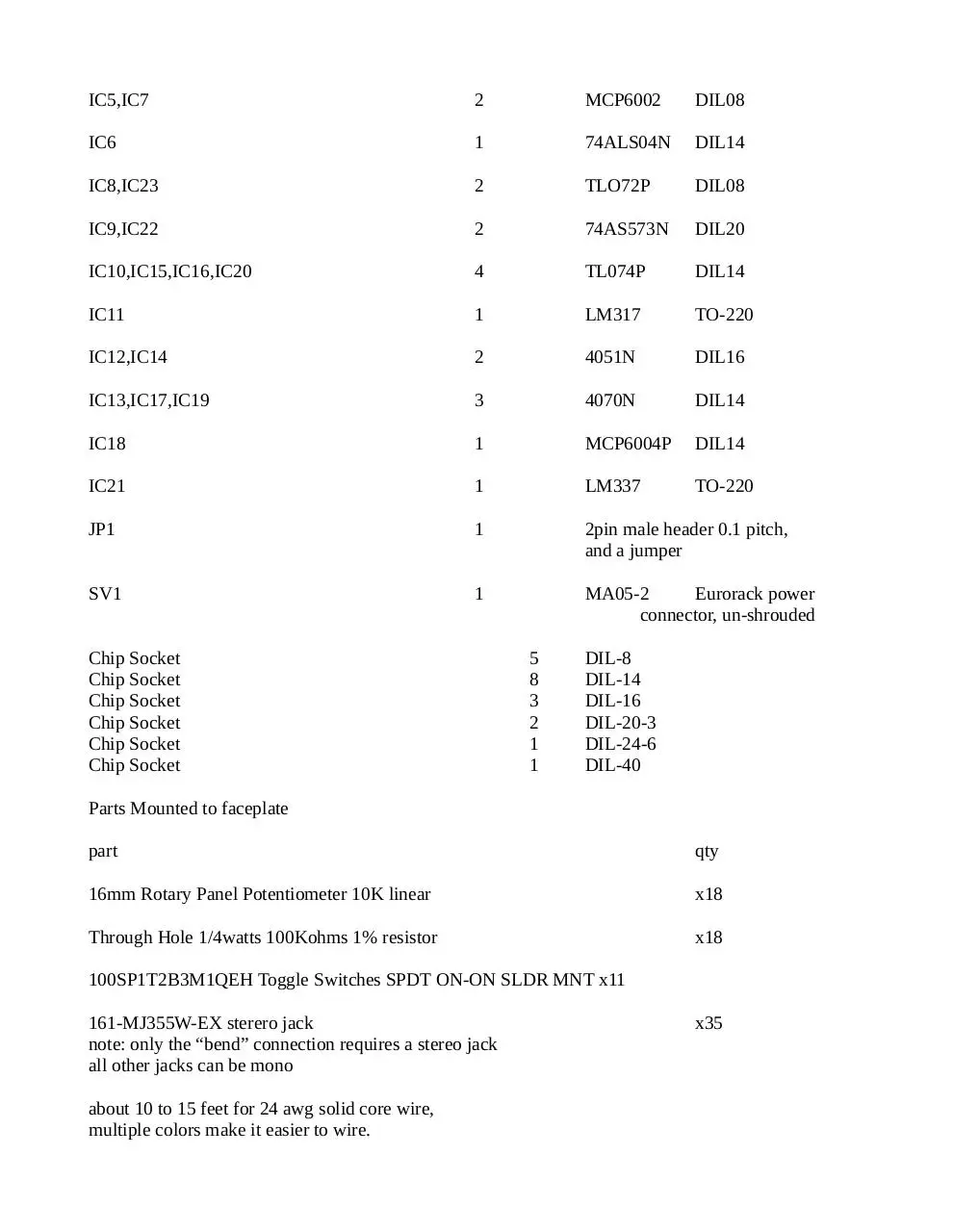
IC5,IC7
2
MCP6002
DIL08
IC6
1
74ALS04N
DIL14
IC8,IC23
2
TLO72P
DIL08
IC9,IC22
2
74AS573N
DIL20
IC10,IC15,IC16,IC20
4
TL074P
DIL14
IC11
1
LM317
TO-220
IC12,IC14
2
4051N
DIL16
IC13,IC17,IC19
3
4070N
DIL14
IC18
1
MCP6004P
DIL14
IC21
1
LM337
TO-220
JP1
1
2pin male header 0.1 pitch,
and a jumper
SV1
1
MA05-2
Eurorack power
connector, un-shrouded
Chip Socket
Chip Socket
Chip Socket
Chip Socket
Chip Socket
Chip Socket
5
8
3
2
1
1
DIL-8
DIL-14
DIL-16
DIL-20-3
DIL-24-6
DIL-40
Parts Mounted to faceplate
part
qty
16mm Rotary Panel Potentiometer 10K linear
x18
Through Hole 1/4watts 100Kohms 1% resistor
x18
100SP1T2B3M1QEH Toggle Switches SPDT ON-ON SLDR MNT x11
161-MJ355W-EX sterero jack
note: only the “bend” connection requires a stereo jack
all other jacks can be mono
about 10 to 15 feet for 24 awg solid core wire,
multiple colors make it easier to wire.
x35
This kit comes with the PCB, face plate, pre-programed Micro-controller, YM3812 and YM3014.
All other parts are builder supplied
Tools required: wire cutters, wire strippers, a small screw driver, needle nose pliers, fine tip tweezers.
And a soldering iron with a fine tip, solder. A fume extractor is always recommended. A volt meter is
needed at the end to calibrate the voltage reference rails
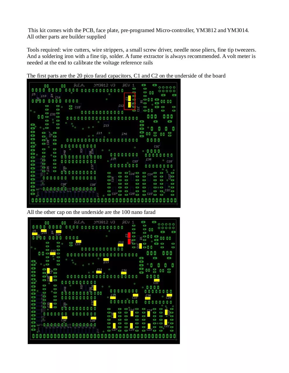
The first parts are the 20 pico farad capacitors, C1 and C2 on the underside of the board
All the other cap on the underside are the 100 nano farad
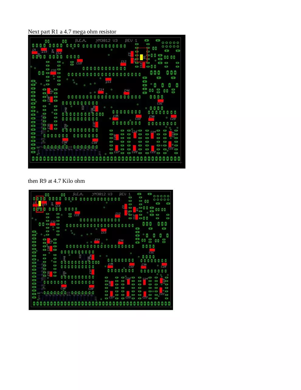
Next part R1 a 4.7 mega ohm resistor
then R9 at 4.7 Kilo ohm
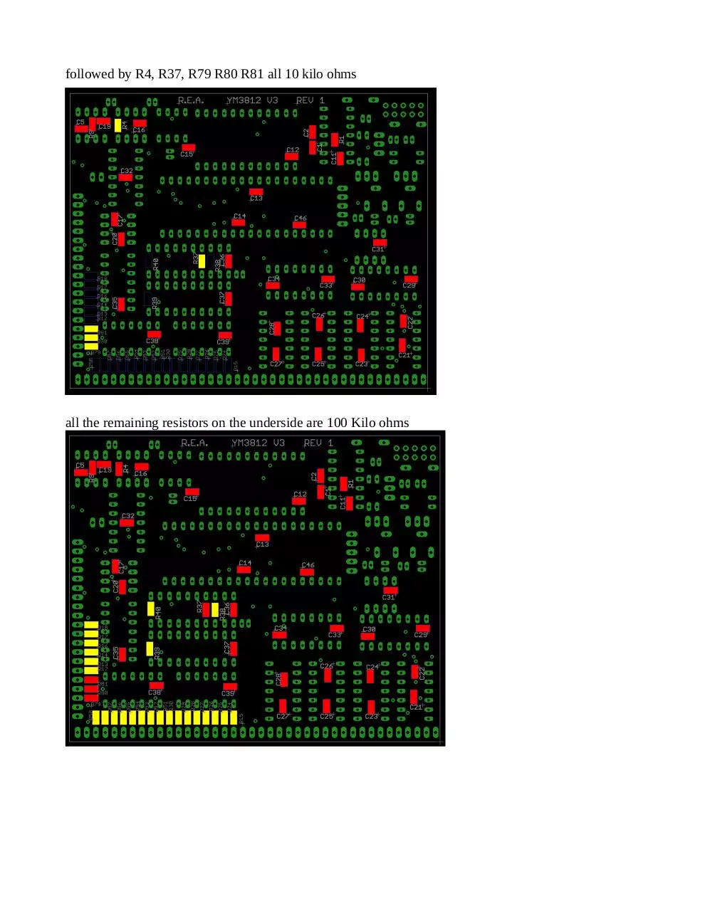
followed by R4, R37, R79 R80 R81 all 10 kilo ohms
all the remaining resistors on the underside are 100 Kilo ohms
Now we flip the board over and start with the parts on the top side.
Starting with C3 at one thousand pico farads.
and then C4 at 2200 pico farads
R0 and R36 both 1 Kilo ohm
R10 at 33 kilo ohm
R2 and R3 at 22 kilo ohm
R71 R72 and R73 at 10 kilo ohm
all the remaining SMT resistors are 100 kilo ohms
the last SMT part, the 3.58 mhz crystal
Next is the step of adding the chip sockets
next parts are the two 10 kilo ohm trimmer pots R23 and R36
followed by the 6 diodes all 1N4007 type. Note the polarity on the PCB
10 micro farad caps are next, the long leg goes to the plus sign on the PCB
Now IC1 the 7805
IC21 the LM337
IC11 the LM317
the last parts on the board are jumper JP1 and the power connector
Now before we add any chips calibrating the voltage references in important. First connect the power
jack and power up the board. Now take a volt meter and connect it to the last two pins on the left of the
PCB. Adjust the trimmer pot on the right until the meter reads negative 5 volts, being within a few
hundredths should be good enough
now measure the voltage between pins 19 and 20 on the PCB and adjust with the potentiometer on the
left until the meter read positive 5 volts
Start the faceplate by attaching all the potentiometers, switches and jacks as shown
Wire the voltage buses together as shown
Each jack is wired to its corresponding potentiometer as shown
With a 100K resistor to the center connection of the potentiometer
Connections from the PCB to the faceplate are shown below
Completed connections will look something like this
Now add the chips, put it in your rack, and enjoy
Download YM3812 V3 Build Guide Rev 1 3
YM3812 V3 Build Guide Rev 1_3.pdf (PDF, 3.83 MB)
Download PDF
Share this file on social networks
Link to this page
Permanent link
Use the permanent link to the download page to share your document on Facebook, Twitter, LinkedIn, or directly with a contact by e-Mail, Messenger, Whatsapp, Line..
Short link
Use the short link to share your document on Twitter or by text message (SMS)
HTML Code
Copy the following HTML code to share your document on a Website or Blog
QR Code to this page

This file has been shared publicly by a user of PDF Archive.
Document ID: 0001908925.