Installation Guide (PDF)
File information
Author: Technical Communications
This PDF 1.4 document has been generated by Adobe InDesign CC 2014 (Windows) / Adobe PDF Library 11.0, and has been sent on pdf-archive.com on 24/06/2016 at 18:21, from IP address 99.227.x.x.
The current document download page has been viewed 678 times.
File size: 13.26 MB (104 pages).
Privacy: public file


File preview
INSTALLATION
GUIDE
Big Ass Fan ® 4900
For help, call 855-490-3048 or
email retail.help@bigasssolutions.com
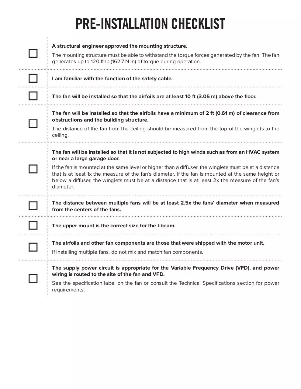
PRE-INSTALLATION CHECKLIST
A structural engineer approved the mounting structure.
The mounting structure must be able to withstand the torque forces generated by the fan. The fan
generates up to 120 ft·lb (162.7 N·m) of torque during operation.
I am familiar with the function of the safety cable.
The fan will be installed so that the airfoils are at least 10 ft (3.05 m) above the floor.
The fan will be installed so that the airfoils have a minimum of 2 ft (0.61 m) of clearance from
obstructions and the building structure.
The distance of the fan from the ceiling should be measured from the top of the winglets to the
ceiling.
The fan will be installed so that it is not subjected to high winds such as from an HVAC system
or near a large garage door.
If the fan is mounted at the same level or higher than a diffuser, the winglets must be at a distance
that is at least 1x the measure of the fan’s diameter. If the fan is mounted at the same height or
below a diffuser, the winglets must be at a distance that is at least 2x the measure of the fan’s
diameter.
The distance between multiple fans will be at least 2.5x the fans’ diameter when measured
from the centers of the fans.
The upper mount is the correct size for the I-beam.
The airfoils and other fan components are those that were shipped with the motor unit.
If installing multiple fans, do not mix and match fan components.
The supply power circuit is appropriate for the Variable Frequency Drive (VFD), and power
wiring is routed to the site of the fan and VFD.
See the specification label on the fan or consult the Technical Specifications section for power
requirements.
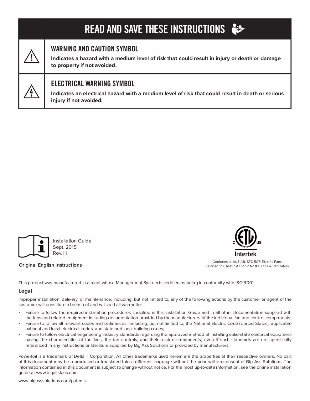
READ AND SAVE THESE INSTRUCTIONS
WARNING AND CAUTION SYMBOL
Indicates a hazard with a medium level of risk that could result in injury or death or damage
to property if not avoided.
ELECTRICAL WARNING SYMBOL
Indicates an electrical hazard with a medium level of risk that could result in death or serious
injury if not avoided.
Installation Guide
Sept. 2015
Rev. H
Original English Instructions
Conforms to ANSI/UL STD 507: Electric Fans
Certified to CAN/CSA C22.2 No.113: Fans & Ventilators
This product was manufactured in a plant whose Management System is certified as being in conformity with ISO 9001.
Legal
Improper installation, delivery, or maintenance, including, but not limited to, any of the following actions by the customer or agent of the
customer will constitute a breach of and will void all warranties:
• Failure to follow the required installation procedures specified in this Installation Guide and in all other documentation supplied with
the fans and related equipment including documentation provided by the manufacturers of the individual fan and control components;
• Failure to follow all relevant codes and ordinances, including, but not limited to, the National Electric Code (United States), applicable
national and local electrical codes, and state and local building codes;
• Failure to follow electrical engineering industry standards regarding the approved method of installing solid-state electrical equipment
having the characteristics of the fans, the fan controls, and their related components, even if such standards are not specifically
referenced in any instructions or literature supplied by Big Ass Solutions or provided by manufacturers.
Powerfoil is a trademark of Delta T Corporation. All other trademarks used herein are the properties of their respective owners. No part
of this document may be reproduced or translated into a different language without the prior written consent of Big Ass Solutions. The
information contained in this document is subject to change without notice. For the most up-to-date information, see the online installation
guide at www.bigassfans.com.
www.bigasssolutions.com/patents
IMPORTANT SAFETY INSTRUCTIONS
TO REDUCE THE RISK OF FIRE, ELECTRIC SHOCK, OR INJURY TO PERSONS, OBSERVE THE FOLLOWING:
WARNING: Installation work and electrical wiring must be done by qualified person(s) in accordance with all applicable
codes and standards.
WARNING: When cutting or drilling into a wall or ceiling, do not damage electrical wiring and other hidden utilities.
CAUTION: The installation of a Big Ass Fan must be in accordance with the requirements specified in this installation
manual and with any additional requirements set forth by the National Electric Code (NEC), ANSI/NFPA 70-2014, and all
local codes. Code compliance is ultimately YOUR responsibility!
WARNING: The fan VFDs contain high voltage capacitors that take time to discharge after removal of mains supply.
Before working on the VFD, ensure isolation of mains supply from line inputs at the VFD’s disconnect. Wait three (3)
minutes for capacitors to discharge to safe voltage levels. Failure to do so may result in personal injury or death. NOTE:
Darkened display LEDs are not an indication of safe voltage levels.
CAUTION: Exercise caution and common sense when powering the fan. Do not connect the fan to a damaged or hazardous
power source. Do not attempt to resolve electrical malfunctions or failures on your own. Contact Big Ass Fans if you have
any questions regarding the electrical installation of this fan.
WARNING: To reduce the risk of fire, electric shock, and injury to persons, Big Ass Fans must be installed with Big Ass
Fan supplied controllers that are marked (on their cartons) to indicate the suitability with this model. Other parts cannot
be substituted.
CAUTION: When service or replacement of a component in the fan requires the removal or disconnection of a safety
device, the safety device is to be reinstalled or remounted as previously installed.
WARNING: Risk of fire, electric shock, or injury to persons during cleaning and user-maintenance! Disconnect the
appliance from the power supply before servicing.
WARNING: Use this unit only in the manner intended by the manufacturer. If you have questions, contact the manufacturer.
WARNING: Before servicing or cleaning unit, switch power off at service panel and lock the service disconnecting means
to prevent power from being switched on accidentally. When the service disconnecting means cannot be locked, securely
fasten a prominent warning device, such as a tag, to the service panel.
CAUTION: Do not bend the airfoils when installing, adjusting, or cleaning the fan. Do not insert foreign objects between
rotating airfoils.
WARNING: Stay alert and use common sense when installing fans. Do not install fans if tired or under the influence of
drugs, alcohol, or medication. A moment of inattention while installing fans may result in serious personal injury.
CAUTION: The installation of this fan requires the use of some power tools. Follow the safety procedures found in the
owner’s manual for each of these tools and do not use them for purposes other than those intended by the manufacturer.
CAUTION: The Big Ass Fans product warranty will not cover equipment damage or failure caused by improper installation.
WARNING: This appliance is not intended for use by persons (including children) with reduced physical, sensory or mental
capabilities, or lack of experience and knowledge, unless they have been given supervision or instruction concerning use
of the appliance by a person responsible for their safety. Children should be supervised to ensure that they do not play
with the appliance.
ATTENTION: If installing the fan in the United States, the fan must be installed per the following National Fire Protection
Association (NFPA) guidelines:
• The fan must be centered approximately between four adjacent sprinklers.
• The vertical distance from the fan to the sprinkler deflector must be at least 3 ft (91.4 cm).
• The fan must be interlocked to shut down immediately upon receiving a waterflow signal from the alarm system.
WARNING: To reduce the risk of fire, electric shock, or personal injury, mount directly to a structural framing member.
Leave this installation guide with the owner of the fan after installation is complete.
CONTENTS
Introduction
Safety Instructions........................................................................................................... ii
About Big Ass Solutions...............................................................................................iv
Technical Specifications
Technical Specifications.................................................................................................1
Before Installing Your Fan
Tools................................................................................................................................... 2
Power Supply Guidelines............................................................................................. 2
Power Wiring Guidelines.............................................................................................. 2
Hardware...........................................................................................................................3
Parts....................................................................................................................................3
Fan Diagram
Fan Diagram.....................................................................................................................4
Where to Install Your
Fan
Clearance Guidelines.................................................................................................... 5
Clearance from HVAC Equipment and Radiant Heaters..................................... 6
Understanding Airflow Patterns..................................................................................7
Installation
Overview.......................................................................................................................... 9
1a. Prepare the I-Beam................................................................................................10
1b. Prepare the Bar Joists........................................................................................... 11
2. Directly Mount Main Fan Unit to Angle Irons.................................................. 14
3a. Attach Upper Mount to I-Beam........................................................................... 15
3b. Attach Upper Mount to Angle Irons.................................................................. 16
4. Attach the Extension Tube................................................................................... 17
5. Secure the Safety Cable...................................................................................... 17
6. Attach Lower Yoke................................................................................................. 18
7. Attach Main Fan Unit............................................................................................. 18
8. Confirm Orientation............................................................................................... 18
9. Mount the Variable Frequency Drive (VFD).................................................... 19
10. Wire the Fan and VFD..........................................................................................20
11. Install the Airfoils...................................................................................................20
Wiring Diagrams &
Electrical Guidelines
Electrical Safety Instructions...................................................................................... 21
VFD Wiring: 100–125 V, 1 Ф.......................................................................................22
VFD Wiring: ESFR (Early Suppression Fast Response)...................................... 23
Operating the Fan
Starting and Stopping the Fan.................................................................................. 24
Adjusting Fan Speed................................................................................................... 24
Reversing Direction of Fan Rotation....................................................................... 24
Heating Season & Cooling Season.........................................................................25
Preventive
Maintenance
Annual Preventive Maintenance..............................................................................26
General Preventive Maintenance............................................................................26
Annual Maintenance Checklist................................................................................. 27
Troubleshooting
General Troubleshooting...........................................................................................29
Troubleshooting the VFD...........................................................................................30
Warranty
Warranty Policy............................................................................................................. 35
Warranty Return Instructions..................................................................................... 39
Warranty Claim Form Instructions............................................................................40
Warranty Claim Form.................................................................................................... 41
Responsibility Agreement.......................................................................................... 42
You’ve made a great choice! Big Ass Fans® are an efficient, cost-effective and seriously cool way to stay comfortable
and save energy all year long. More importantly, everything about your new fan—from the design of the motor to
the angle of the airfoils—is based on extensive research, testing, and innovative engineering. It will keep you and
your space comfortable for years to come.
Questions or comments? We’d love to talk. Just call 855-490-3048 or email retail.help@bigasssolutions.com.
About Big Ass Solutions
Our provocative moniker originated with the massive overhead fans we perfected to bring comfort and energy
savings to large industrial buildings. Today, though, Big Ass Solutions is much more than industrial—and much
more than Big Ass Fans or Big Ass Light. Big Ass Fans means quality, form, and function to solve problems in
the built environment. It means having a herd of engineers on staff and the world’s only R&D facility dedicated
to testing air movement on a grand scale. It means speaking to our customers directly to understand and solve
their problems—if they need air movement, we do it bigger and better. If they need light, we make incredibly
bright, long-lasting LEDs. But mostly it means an insatiable drive to improve, engineer, design, test, re-engineer,
re-design, and re-test until we get it just right. That’s why there’s No Equal™.
TECHNICAL SPECIFICATIONS
Diameter Motor Size
14 ft
(4.3 m)
1.0 hp
(0.75 kW)
Minimum Circuit Size
Full Load Amps
Maximum
Speed
Airfoil
Length
Suggested
Distance from
Ceiling
20 A @ 100–125 V, 1 Φ
11.0 A
101 RPM
76”
(193 cm)
5 ft
(1.5 m)
Motor
• 1 hp motor
• NEMA Design B
• 208/230/460 Volts AC
• 1725 RPM
• 60 Hz, 3-phase
• Rating: 40º C Ambient–Continuous
Reduction gear
• Concentric Helical Gear Reducer
• Gear Hardened to 58-62 Rockwell C
• Precision finished for low noise and long service life
• Double seals keep oil in and contaminants out
• Lubricated for life with synthetic oil
WWW.BIGASSSOLUTIONS.COM
© 2015 DELTA T CORP.
ALL RIGHTS RESERVED.
1
BEFORE INSTALLING YOUR FAN
Read the following pre-installation procedures and checks to ensure you have all necessary items for installation.
Tools
The fan weighs 150 lbs (60 kg). A suitable means for lifting the weight of the fan, such as a scissor lift, at least two
personnel, and the following tools will be required. Note: Depending on your application, additional tools may be
required.
☐☐ Standard wrench set
☐☐ 1/4” nut driver
☐☐ Standard socket set and ratchet
☐☐ 5/16” nut driver
☐☐ Torque wrench capable of 40 ft·lb (54.2 N·m) & 3/4” socket
☐☐ #10 to #14 AWG strippers
☐☐ Phillips and flat head screwdrivers
☐☐ Medium channel locks
☐☐ Standard allen wrench set
☐☐ Multimeter
Power supply guidelines
If you are unfamiliar or uncomfortable with the installation of electrical components, do not attempt to install the
fan without an electrician. This guide is merely a recommendation of proper installation.
✓✓ Circuit Requirements. Refer to the Technical Specifications section and fan label for appropriate circuit
requirements for your fan.
✓✓ Conduit. Controller output/motor input leads cannot share a conduit with any other controller’s AC supply feed.
Power wiring guidelines
✓✓ To reduce the risk of electric shock, wiring should be performed by a qualified electrician. Incorrect assembly
can cause electric shock or damage to the motor or controller.
✓✓ The electrical installation of the fan must be in accordance with the National Electrical Code, ANSI/NFPA 702014, if applicable, and all local codes.
✓✓ If extending the controller output/motor input leads, use stranded wire.
✓✓ See the Wiring Diagrams & Electrical Guidelines section for detailed electrical requirements.
2
WWW.BIGASSSOLUTIONS.COM
© 2015 DELTA T CORP.
ALL RIGHTS RESERVED.
Hardware
Fan hardware for hanging the fan and airfoils is provided on hardware boards. Verify you have all of the following
required hardware before beginning the installation process. If you are missing any piece required for installation,
contact Big Ass Fans Customer Service. Note: No hardware substitutions are acceptable.
Mounting Hardware Board1
Upper Mount Hardware
• (4) 1/2-13 x 2” GR 8 Bolts
• (8) 1/2” Flat Washers
• (4) 1/2-13 Nylock Nuts
Extension Tube Hardware
• (2) 1/2-13 x 4-1/2” GR 8 Bolts
• (4) 1/2” Flat Washers
• (2) 1/2-13 Nylock Nuts
Lower Yoke Hardware
• (2) 1/2-13 x 4-1/2” GR 8 Bolts
• (4) 1/2” Flat Washers
• (2) 1/2-13 Nylock Nuts
Safety Cable Shackle
Main Fan Unit, Airfoil, & Winglet Hardware Boards
Main Fan Unit Hardware
• (4) 1/2-13 x 1-3/4” GR 8 Bolts
• (8) 1/2” Flat Washers
• (4) 1/2-13 Nylock Nuts
Airfoil Hardware
• (12) 5/16-18 x 2” GR 8 Bolts
• (24) 5/16” Flat Washers
• (12) 5/16-18 Nylock Nuts
Winglet Hardware
• (6) 10-24 x 1/2” Bolts
• (6) 10-24 x 3/4” Barrels
1. Square washers are included and are only used if you are mounting the fan to angle irons. The number of square washers used depends on the number of angle irons used.
Parts
Check that the fan boxes have all the parts before beginning installation. If you ordered multiple fans, be sure
to keep the components of each fan together. The fans each have differently rated components that are not
interchangeable. Note: Illustrations are not to scale.
(2) Beam Clip
(2) Spacer
(6) Airfoils
Upper Mount
Lower Yoke
(6) Winglets
Variable Frequency
Drive (VFD)1
Fire Relay2
(6) Airfoil Retainers
1. The VFD includes a 10-ft (3 m) pre-attached AC supply cord. An Electronic
Programming Module (EPM) is installed in the VFD.
2. The fire relay is required for fans that will be installed in buildings that have
a fire sprinkler system. See the Wiring Diagrams & Electrical Guidelines
section for fire relay wiring details.
Main Fan Unit3
Extension Tube & Safety Cable4
WWW.BIGASSSOLUTIONS.COM
3. The fan includes a pre-attached motor cord.
4. The safety cable is attached to the extension tube.
© 2015 DELTA T CORP.
ALL RIGHTS RESERVED.
3
Download Installation Guide
Installation Guide.pdf (PDF, 13.26 MB)
Download PDF
Share this file on social networks
Link to this page
Permanent link
Use the permanent link to the download page to share your document on Facebook, Twitter, LinkedIn, or directly with a contact by e-Mail, Messenger, Whatsapp, Line..
Short link
Use the short link to share your document on Twitter or by text message (SMS)
HTML Code
Copy the following HTML code to share your document on a Website or Blog
QR Code to this page

This file has been shared publicly by a user of PDF Archive.
Document ID: 0000393810.