01 506 manuscript cable sizing 1 (PDF)
File information
Title: Microsoft Word - 01 506 manuscript cable sizing 1
Author: TH Sutikno
This PDF 1.5 document has been generated by PScript5.dll Version 5.2.2 / Acrobat Distiller 10.0.0 (Windows), and has been sent on pdf-archive.com on 25/09/2016 at 06:03, from IP address 36.73.x.x.
The current document download page has been viewed 701 times.
File size: 246.72 KB (7 pages).
Privacy: public file


File preview
Bulletin of Electrical Engineering and Informatics
ISSN: 2302-9285
Vol. 5, No. 1, March 2016, pp. 1~7, DOI: 10.11591/eei.v5i1.506
1
Effective Cable Sizing model for Building Electrical
Services
M. Pratap Nair1, K. Nithiyananthan*2
Faculty of Engineering and Computer Technology, AIMST University, Bedong, Kedah
*Corresponding author, e-mail: pratapsamrat@gmail.com1, nithiieee@yahoo.co.in2
Abstract
This paper mainly focuses on the sizing of electrical cables (i.e.cross-sectional area) and its
accomplishment in various international standards. Cable sizing methods are at variance across
international standards. For example, International Electrotechnical Commission (IEC), National Electrical
Code (NEC), British Standard (BS) and Institute of Electrical and Electronics Engineers (IEEE). The basic
philosophy underlying any cable sizing calculation is to develop a procedure model on cable sizing. The
main objective of this research work is to develop effective cable sizing model for building services.
Keywords: Conductor, Cable sizing, Ampacity, Current carrying capacity, Bunch, Voltage drop
1. Introduction
There are four primary reasons that the cable sizing is very important at design stage.
First and foremost, cable sizing is important to operate continuously under full load condition
without being damaged. Moreover, it is necessary to withstand the worst short circuit currents
flowing through the cable. Ensure that the protective devices are effective during an earth fault.
Ensure that, the supply to the load with a suitable voltage and avoid excessive voltage drops.
2. Cable Selection, Sizing and Other Parameters
Sizing Cable sizing methods follow the unchanged basic step process. Firstly, it’s vital
to gather data about the cables, installation surroundings, and the load that it will carry. In
addition, it’s crucial to find the current carrying capacity (A, ampere) and voltage drop per
ampere meter (MV/A/m) of the cable. The current carrying capacity of a cable is the maximum
current that can flow continuously through a cable without damaging the cable's insulation and
other components. Short circuit temperature rise and earth fault loop impedance are significant
factors to verify the cable size [1].
Every conductors and cables except superconductor have some amount of resistance.
This resistance is directly proportional to the length and inversely proportional to the diameter of
the conductor.
R α L/a
[Laws of resistance R = ρ (L/a)]
(1)
Voltage drop occurs in every conductor as the current flows through it. According to
Institute of Electrical and Electronics Engineers (IEEE) rule B-23, at any point between a power
supply terminal and installation, voltage drop should not increase above 2.5% of provided
(supply) voltage.
The component parts that make up of the cable for instance conductors, insulation, and
bedding, must be capable of withstanding the temperature rise and heat emanating by the
cable. Table 1 shows the current carried by any conductor for continuous periods during normal
operation shall be such that the suitable temperature limits.
Received August 1, 2015; Revised October 23, 2015; Accepted November 16, 2015
2
ISSN: 2089-3191
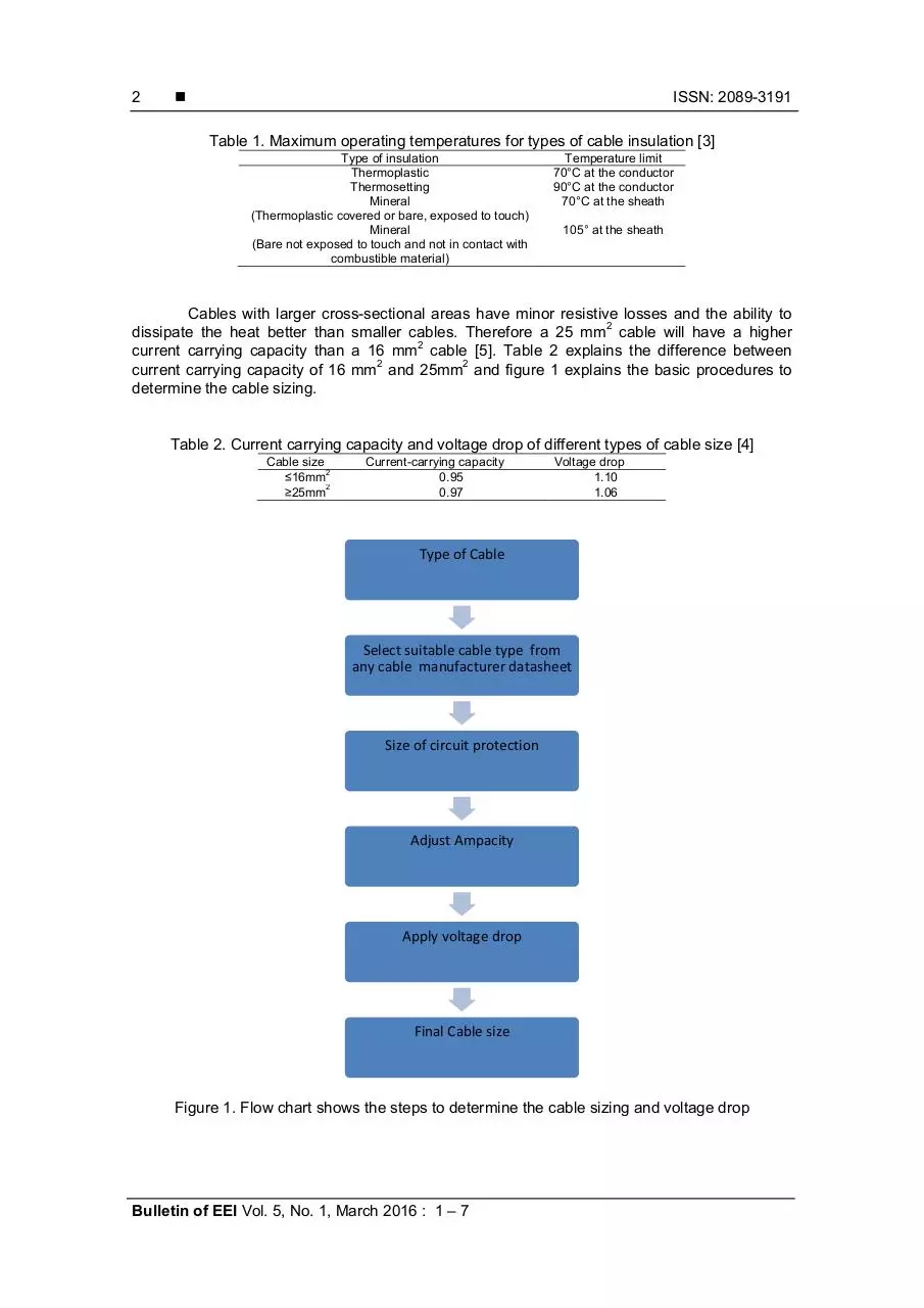
Table 1. Maximum operating temperatures for types of cable insulation [3]
Type of insulation
Thermoplastic
Thermosetting
Mineral
(Thermoplastic covered or bare, exposed to touch)
Mineral
(Bare not exposed to touch and not in contact with
combustible material)
Temperature limit
70°C at the conductor
90°C at the conductor
70°C at the sheath
105° at the sheath
Cables with larger cross-sectional areas have minor resistive losses and the ability to
dissipate the heat better than smaller cables. Therefore a 25 mm2 cable will have a higher
current carrying capacity than a 16 mm2 cable [5]. Table 2 explains the difference between
current carrying capacity of 16 mm2 and 25mm2 and figure 1 explains the basic procedures to
determine the cable sizing.
Table 2. Current carrying capacity and voltage drop of different types of cable size [4]
Cable size
2
≤16mm
2
≥25mm
Current-carrying capacity
0.95
0.97
Voltage drop
1.10
1.06
Type of Cable
Select suitable cable type from
any cable manufacturer datasheet
Size of circuit protection
Adjust Ampacity
Apply voltage drop
Final Cable size
Figure 1. Flow chart shows the steps to determine the cable sizing and voltage drop
Bulletin of EEI Vol. 5, No. 1, March 2016 : 1 – 7
Bulletin of EEI
ISSN: 2302-9285
3
3. Cable Sizing Model & Formulation [2]
International standards and cable manufacturers will provide derating factors for a
range of installation conditions, for example, ambient or soil temperature, grouping or bunching
of cables, and soil thermal resistivity [6]. The installed current rating is calculated by multiplying
the base current rating with each of the derating factors.
Ic= Ib x kd
(2)
Where Ic is the installed current rating (A), Ib is the base current rating (A) and Kd are the
product of all the derating factors.
Motors are normally protected by a separate thermal overload (TOL) relay.
Consequently the upstream protective device circuit breaker is not required to protect the cable
against overloads. As a result, the cables need only to be sized to cater for the full load current
of the motor.
Il ≤ Ic
(3)
Where Il is the full load current (A), Ip is the protective device rating (A) Ic is the installed cable
current rating (A).
Cable Impedances are a function of the cable size (cross-sectional area) and the length
of the cable. Most cable manufacturers will quote a cable’s resistance and reactance in Ω/km.
The following typical cable impedances for low voltage AC single core and multicore cables can
be used in the absence of any other data.
For single circuit:
(4)
Where the protective device is is a semi enclosed fuse to BS 3036, Cf=0.725 otherwise Cf=1.
The cable installation method is ‘in a duct in the ground’ or ‘buried direct’, Cc= 0.9. For cables
installed above ground Cc= 1. Ca= Ambient temperature, Cs= Soil resistivity, Cd=dept of burial,
Ci= Thermal Insulation, Ib= the design of current of the circuit, It= the value of current for ingle
circuit at ambient temperature. For cables installed above ground Cs and Cd =1.
For group:
(5)
For cables having cross sectional area 16mm2 or less, the design value of mV/A/m is obtained
by multiplying the tabulated value by factor Ct given by:
(6)
For AC three phase system:
(7)
Where V3ø is the three phase voltage drop (V), I is the nominal full load or starting current as
Effective Cable Sizing model for Building Electrical Services (M. Pratap Nair)
4
ISSN: 2089-3191
applicable (A), Rc is the AC resistance of the cable (Ω/km), Xc is the AC resistance of the cable
(Ω/km) cos ø is the load power factor (pu) L is the length of the cable (m).
For AC single phase system:
(8)
It is standards to indicate maximum permissible voltage drops, which is the maximum
voltage drop that is permissible across a cable. If the cable exceeds this voltage drop, then a
bigger cable size should be preferred.
Greatest voltage drops across a cable are specified because load consumers will have
an input voltage tolerance range. If the voltage of the electrical device is lower than, its rated
minimum voltage, then the appliance may not work appropriately.
It may be more precise to calculate the maximum length of a cable for a particular
conductor size given a maximum permissible voltage drop 5% of nominal voltage at full load
rather than the voltage drop itself. To construct tables showing the maximum lengths
corresponding to different cable sizes in order to speed up the selection of similar type cables.
[2]
For a three phase system:
(9)
For a single phase system:
(10)
A high amount of current will flow through a cable for a short time when there is short
circuit happens in the circuit. This surge in current flow causes a temperature rise within the
cable.
High temperatures can trigger unnecessary reactions in the cable insulation, sheath
materials and other components, which can degrade the condition of the cable. Bigger cable
cross-sectional area can dissipate higher fault currents. Therefore, cables should be sized to
withstand the largest short circuit.
The minimum cable size due to short circuit temperature rise is typically calculated with
an equation of the form:
(11)
The temperature rise constant is calculated based on the material properties of the conductor
and the initial and final conductor temperatures as per equation 12.
(12)
Bulletin of EEI Vol. 5, No. 1, March 2016 : 1 – 7
Bulletin of EEI
ISSN: 2302-9285
5
Table 3. Examples of methods of installation [4]
No
Description
Method of installation
1
Insulated conductors or singlecore cables in conduit in a
thermally insulated wall
The wall consists of outer weatherproof skin,
thermal insulation and an inner skin. Heat from
the cables is assumed to escape through the
inner skin only.
2
Multi-core cables in conduit in a
thermally insulated wall
4
Insulated conductors or singlecore cables in conduit on a
wooden, or masonry wall or
spaced less than 0,3 x conduit
diameter from it
Multi-core cable in conduit on a
wooden, or masonry wall or
spaced less than 0,3 x conduit
diameter
from it
Single-core or multi-core cables:
- fixed on, or spaced less than
0.3 x cable diameter from a
wooden wall
The wall consists of outer weatherproof skin,
thermal insulation and an inner skin. Heat from
the cables is assumed to escape through the
inner skin only.
The conduit is mounted on a wooden wall.
Conduit is fixed to a masonry wall the current
carrying capacity of the non sheated or
sheathed cable may be higher.
5
20
Methods of
installation
The conduit is mounted on a wooden wall.
Conduit is fixed to a masonry wall the current
carrying capacity of the non sheated or
sheathed cable may be higher.
Cable mounted on a wooden wall so that the
gap between the cable and the surface is less
than 0.3 times the cable diameter. Where the
cable is fixed to a embedded in a masonry wall
the current-carrying capacity may be higher.
30
On unperforated tray
Cable mounted on a wooden wall so that the
gap between the cable and the surface is less
than 0.3 times the cable diameter. Where the
cable is fixed to a embedded in a masonry wall
the current-carrying capacity may be higher.
31
On perforated tray
The cable is supported such that the total heat
dissipation is not impeded. A clearance
between a cable and any adjacent surface of
at least 0.3 times the cable, external diameter
for multicore cables 1.0 times the cable
diameter for single-core cables
36
Bare or insulated conductors on
insulators
70
Multi-core cables in conduit or in
cable ducting in the ground
71
Single-core cable in conduit or in
cable ducting in the ground
The cable is supported such that the total heat
dissipation is not impeded. A clearance
between a cable and any adjacent surface of
at least 0.3 times the cable, external diameter
for multicore cables 1.0 times the cable
diameter for single-core cables
The cable is supported such that the total heat
dissipation is not impeded. A clearance
between a cable and any adjacent surface of
at least 0.3 times the cable, external diameter
for multicore cables 1.0 times the cable
diameter for single-core cables
The cable is supported such that the total heat
dissipation is not impeded. A clearance
between a cable and any adjacent surface of
at least 0.3 times the cable, external diameter
for multicore cables 1.0 times the cable
diameter for single-core cables
An illustration of some of the many different wiring systems and methods of installation
is provided in Table 3 where grouping installation methods having the same characteristics
Effective Cable Sizing model for Building Electrical Services (M. Pratap Nair)
6
ISSN: 2089-3191
relative to the current-carrying capacities of the wiring systems. Table 4 shows the correction
factor k4 for different configuration of cables which has been laid directly.
Table 4. The values of correction factor k4 for different configurations of cables or conductors
laid directly in the ground [2].
a
Number of
circuits
Nil (cables
touching)
0.75
0.65
0.60
0.55
0.50
2
3
4
5
6
Cable to cable clearance (a)
One cable
0.125 m
0.25 m
diameter
0.80
0.85
0.90
0.70
0.75
0.80
0.60
0.70
0.75
0.55
0.65
0.70
0.55
0.60
0.70
0.5 m
0.90
0.85
0.80
0.80
0.80
Figure 2. Reduction factors for more than one circuit, single-core or multi-core cables laid
directly in the ground. [2]
4. Results
Table 5. Voltage drop for different Electrical Components [1]
Low voltage installation supplied
directly from a public low voltage
distribution system
Low voltage installation supplied
from the private LV supply (*)
Lighting
3%
Other Uses
5%
6%
8%
Table 5 explains the voltage drop between the origin of an installation and any load point should
be greater than the values in the table below expressed with respect to the value of the nominal
voltage of installation. [1]
Table 6. Sample of calculation of voltage drop using V=IR
NO
1
FROM
TO
MAX
DIST
(m)
DB
Light
10
DESCRIPTION
POWER
LOAD
VOLT
CURRENT
CSA
(W)
(W)
(V)
(A)
(mm2)
42
84
240
0.35
2.5
mV/A/m
18
DROP
(%)
(v)
0.2
0.38
REMAIN
VOLT
239.63
5. Conclusion
Selecting power cable and types of cables with the sizing of the conductors for specific
applications is a very essential part of the plan of any electrical system. That this task is often
performed with a least amount of effort and with minimum reflection for all of the applicable
Bulletin of EEI Vol. 5, No. 1, March 2016 : 1 – 7
Bulletin of EEI
ISSN: 2302-9285
7
design issues. The consequential catastrophe is that inappropriate selection and sizing can
easily amplify the installed cost of a facility while also dropping the reliability of the complete
system.
This paper highlights on some of the considerations that should be practice for cable
selection each and every time. It then suggests the right design tool to calculate and facilitate
the selection process without resorting to simplifications.
References
[1] IEC 60364-5-52. "Electrical installations in buildings - Part 5-52: Selection and erection of electrical
equipment - Wiring systems" is the IEC standard governing cable sizing. 2009.
[2] National Electricity Code (NEC), 2011.
[3] NFPA 70. "National Electricity Code" is the equivalent standard for IEC 60364 in North America and
includes a section covering cable sizing in Article 300. 2011.
[4] BS 7671. "Requirements for Electrical Installations - IEE Wiring Regulations" is the equivalent
standard for IEC 60364 in the United Kingdom. 2008.
[5] Adetoro, K. Adebayo. ‘Assessment of the Quality of Cables produced in Nigeria’. Global Advanced
Research Journal of Engineering, Technology and Innovation. 2012; 1(4): 097-102.
[6] Coker AJ, Turner WO, Josephs ZT. Electrical Wiring. Redwood Press Limited. 1991: 12 – 28.
Effective Cable Sizing model for Building Electrical Services (M. Pratap Nair)
Download 01 506 manuscript cable sizing 1
01 506 manuscript cable sizing 1.pdf (PDF, 246.72 KB)
Download PDF
Share this file on social networks
Link to this page
Permanent link
Use the permanent link to the download page to share your document on Facebook, Twitter, LinkedIn, or directly with a contact by e-Mail, Messenger, Whatsapp, Line..
Short link
Use the short link to share your document on Twitter or by text message (SMS)
HTML Code
Copy the following HTML code to share your document on a Website or Blog
QR Code to this page

This file has been shared publicly by a user of PDF Archive.
Document ID: 0000486771.