BF375M 24V 1A PSU Insts DFU3750100 rev3 (2) (PDF)
File information
Title: BF375M NEW INSTS2
Author: Andy Green
This PDF 1.5 document has been generated by Adobe PageMaker 6.52 / Acrobat Distiller 5.0.2 for Macintosh, and has been sent on pdf-archive.com on 23/08/2017 at 17:33, from IP address 84.43.x.x.
The current document download page has been viewed 273 times.
File size: 96.06 KB (4 pages).
Privacy: public file


File preview
BF375M
24V 1A REGULATED POWER SUPPLY UNIT
IMPORTANT: READ ALL OF THIS DOCUMENT CAREFULLY BEFORE INSTALLING THIS EQUIPMENT.
The BF375M is a general purpose mains to regulated 24V d.c. power supply
unit (PSU) complete with on-board relay. It has three indicators (mains on,
battery/power supply fault and output triggered).
Two inputs are provided (trigger and hold off). These can be used to control
the internal relay switching the output voltage on or off. This and the PSUs
sophisticated fault monitoring function makes the BF375M ideal for a host
of applications.
Optional back-up batteries can be fitted to the PSU to maintain the output in
the event of mains failure.
TYPICAL EXTRA LOW VOLTAGE CONNECTION DETAILS
Below are examples of three very basic circuits which will suit the needs of most users. It should be noted however that
the BF375M is a very versatile control PSU and many additional and more sophisticated control scenarios can be
implemented if required (see page three for details).
FIG 1: UNSWITCHED LOAD - use these connections to supply constant 24V d.c to a load.
HOLD OFF
TRIGGER
FAULT O/P
0V
N.O.
+24V
LINK
PLK3
FITTED
LOAD
N.C.
FIG 2: SWITCHED LOAD - use these connections to energize the load (e.g. rollerdoor shutter) via the BF375M's
relay when external voltage is applied to its trigger input
HOLD OFF
TRIGGER
FAULT O/P
0V
+5 to 27V d.c.
EXTERNAL
CONTROL
EQUIPMENT
0V
N.O.
+24V
LOAD
N.C.
LINK
PLK3
FITTED
FIG 3 : SWITCHED LOAD - use these connections to de-energize the load (e.g. magnetic door holders) via
the BF375M's relay when external voltage is applied to its trigger input
HOLD OFF
TRIGGER
FAULT O/P
+5 to 27V d.c.
EXTERNAL
CONTROL
EQUIPMENT
0V
0V
N.O.
+24V
N.C.
FIRE ALARM
ancillaries
LOAD
LINK
PLK3
FITTED
Approved Document No. DFU3750100 Rev 3
1 of 4
INSTALLATION
THIS EQUIPMENT MUST ONLY BE INSTALLED AND MAINTAINED BY A SUITABLY SKILLED AND
TECHNICALLY COMPETENT PERSON. THIS EQUIPMENT MUST BE EARTHED.
The PSU must be sited internally with consideration given to the visibility of the indicators and any likelihood of tampering
or vandalism of the equipment. All wiring must be undertaken with respect to the current edition of the IEE Wiring Regs,
16th Ed. (BS 7671 1993) or in accordance with the relevant national wiring rules. If the PSU is to be used as part of a fire
alarm installation, the wiring must also comply with BS5839 Part 1.
The general requirement for the connection of mains to the PSU is fixed wiring using three core cable not less than 0.75mm2,
fed from an isolating switched fuse spur (or a similar disconnection device) fused at 3A. A plug and socket must not be used.
Take the power supply out of its box and undo the two front panel retaining screws with the key supplied. Hinge the
front panel down through 90 degrees and remove the earth connection. Locate the connector plug (PL1) on the main
printed circuit board and firmly pull it off the board. Gently spring the lid over the two hinge bosses and lift the front panel
off. Keep the front panel in a safe, dust free place.
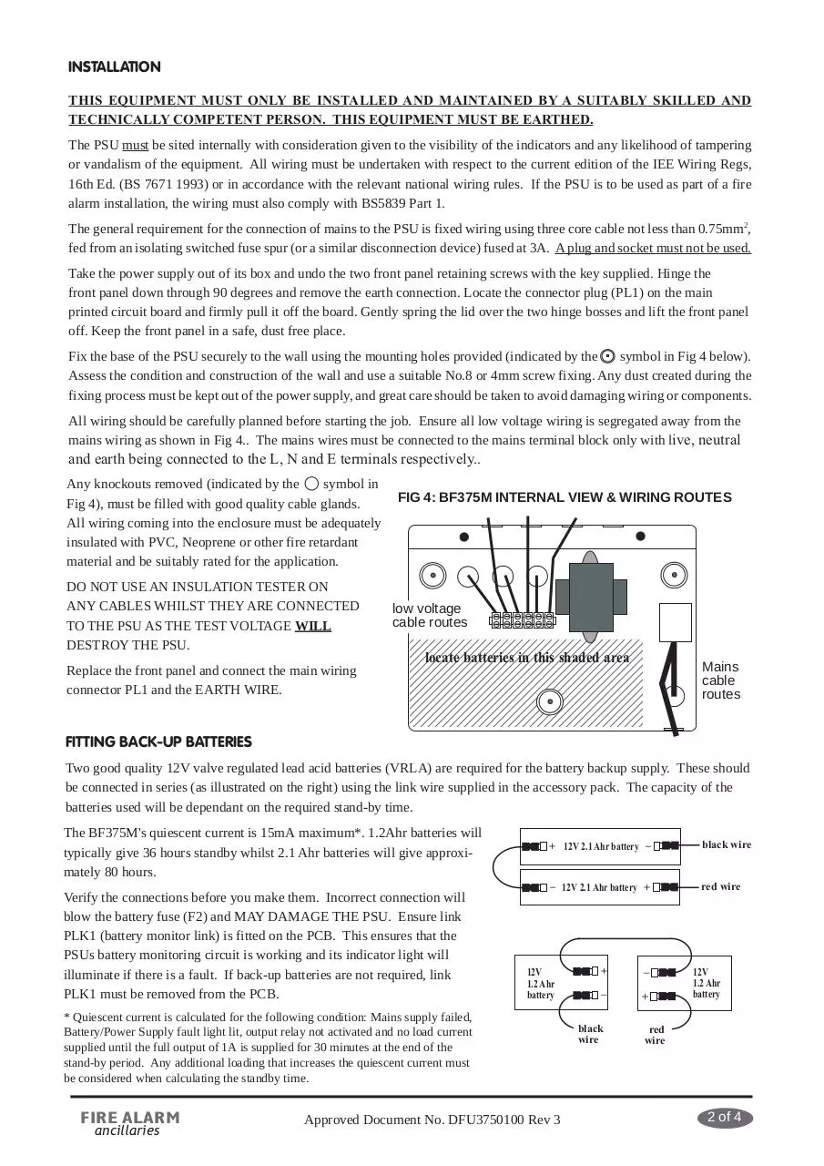
Fix the base of the PSU securely to the wall using the mounting holes provided (indicated by the
symbol in Fig 4 below).
Assess the condition and construction of the wall and use a suitable No.8 or 4mm screw fixing. Any dust created during the
fixing process must be kept out of the power supply, and great care should be taken to avoid damaging wiring or components.
All wiring should be carefully planned before starting the job. Ensure all low voltage wiring is segregated away from the
mains wiring as shown in Fig 4.. The mains wires must be connected to the mains terminal block only with live, neutral
and earth being connected to the L, N and E terminals respectively..
Any knockouts removed (indicated by the
symbol in
Fig 4), must be filled with good quality cable glands.
All wiring coming into the enclosure must be adequately
insulated with PVC, Neoprene or other fire retardant
material and be suitably rated for the application.
DO NOT USE AN INSULATION TESTER ON
ANY CABLES WHILST THEY ARE CONNECTED
TO THE PSU AS THE TEST VOLTAGE WILL
DESTROY THE PSU.
Replace the front panel and connect the main wiring
connector PL1 and the EARTH WIRE.
FIG 4: BF375M INTERNAL VIEW & WIRING ROUTES
low voltage
cable routes
12345678901234567890123456789012
12345678901234567890123456789012
12345678901234567890123456789012
12345678901234567890123456789012
locate batteries in this shaded area
12345678901234567890123456789012
12345678901234567890123456789012
12345678901234567890123456789012
12345678901234567890123456789012
12345678901234567890123456789012
12345678901234567890123456789012
12345678901234567890123456789012
12345678901234567890123456789012
Mains
cable
routes
FITTING BACK-UP BATTERIES
Two good quality 12V valve regulated lead acid batteries (VRLA) are required for the battery backup supply. These should
be connected in series (as illustrated on the right) using the link wire supplied in the accessory pack. The capacity of the
batteries used will be dependant on the required stand-by time.
The BF375M's quiescent current is 15mA maximum*. 1.2Ahr batteries will
typically give 36 hours standby whilst 2.1 Ahr batteries will give approximately 80 hours.
Verify the connections before you make them. Incorrect connection will
blow the battery fuse (F2) and MAY DAMAGE THE PSU. Ensure link
PLK1 (battery monitor link) is fitted on the PCB. This ensures that the
PSUs battery monitoring circuit is working and its indicator light will
illuminate if there is a fault. If back-up batteries are not required, link
PLK1 must be removed from the PCB.
+ 12V 2.1 Ahr battery –
black wire
– 12V 2.1 Ahr battery +
red wire
12V
1.2 Ahr
battery
* Quiescent current is calculated for the following condition: Mains supply failed,
Battery/Power Supply fault light lit, output relay not activated and no load current
supplied until the full output of 1A is supplied for 30 minutes at the end of the
stand-by period. Any additional loading that increases the quiescent current must
be considered when calculating the standby time.
FIRE ALARM
ancillaries
Approved Document No. DFU3750100 Rev 3
+
–
–
+
black
wire
12V
1.2 Ahr
battery
red
wire
2 of 4
SUPPLY OUTPUTS
Dependent on the position of link PLK2 and the status of the BF375M's two inputs, the control relay switches the nominal
24V to the normally closed (N.C.) or normally open (N.O.) outputs, as described in the table below:RELAY NOT ACTIVE
LINK PLK2 POSITION
RELAY ACTIVE
N.C. OUTPUT
N.O. OUTPUT
N.C. OUTPUT
N.O. OUTPUT
SUMMARY
A
B
ON
OFF
OFF
ON
N.C. output switches off when
relay active. N.O. output
switches on when relay active
A
B
ON
OFF
ON
ON
N.C. output permanently on.
N.O. output switches on
when relay active
A
B
ON
ON
OFF
ON
N.C. output switches off
when relay active.
N.O. output permanently on.
INPUTS
TRIGGER INPUT
This input requires a positive voltage of +5 to +27 Vd.c. with respect to 0V to trigger the relay. When this voltage is applied,
the BF375M's trigger indicator is lit and the relay is energised. (See figs 2 & 3 on page 1 for circuit wiring)
HOLD OFF
This optional input is designed for use on failsafe systems.
FIG 5: EXTERNAL HOLD OFF
It requires a constant positive voltage of +5 to +27 Vd.c.
with respect to 0V (typically obtained from a control panel
such as a fire alarm panel).
This voltage MUST be applied to PREVENT the relay
from energising. When the hold off voltage is removed,
the BF375M's trigger indicator is lit and the relay is
energised. See diagram (right).
LINK
PLK3
NOT
FITTED
HOLD OFF
+5 to 27V d.c.
TRIGGER
FAULT O/P
0V
POSITION OF
N.O.
LINK PLK2 IS
+24V
DEPENDENT
N.C.
ON N.O. or N.C.
OPERATION
EXTERNAL
CONTROL
EQUIPMENT
0V
LOAD
If the hold off input is not used, link PLK3 must be fitted so that the hold off voltage is provided internally (this is
the factory default setting).
OTHER APPLICATIONS & CIRCUIT WIRING EXAMPLES
SWITCHING THE RELAY USING EQUIPMENT WITH AN OPEN COLLECTOR OUTPUT
In addition to the methods shown above, it is possible to switch the PSU's relay using control equipment that has an open
collector output (as found on certain makes of fire alarm panels). The open collector output should be connected to the
PSU's hold off input as shown in fig 6.
FIG 6: SWITCHING THE RELAY VIA AN OPEN COLLECTOR OUTPUT
LINK
PLK3
FITTED
POSITION OF
LINK PLK2 IS
DEPENDENT ON
N.O. or N.C.
OPERATION
HOLD OFF
TRIGGER
FAULT O/P
0V
N.O.
+24V
FIRE ALARM
ancillaries
EXTERNAL
CONTROL
EQUIPMENT
N.C.
LOAD
CONTROL EQUIPMENT DRIVE IS OPEN COLLECTOR
TRANSISTOR. THIS TURNS ON UNDER ALARM
CONDITIONS AND PULLS INTERNAL HOLD OFF
VOLTAGE CLOSE TO 0V, TRIGGERING THE RELAY.
LINK PLK3 MUST BE FITTED IF THIS METHOD OF
CONNECTION IS USED
Approved Document No. DFU3750100 Rev 3
3 of 4
EXAMPLE OF FAULT WIRING
HOLD OFF
TRIGGER
FAULT O/P
0V
N.O.
+24V
OTHER
CONNECTIONS
AS REQUIRED
end of line
resistor
OTHER
CONNECTIONS
AS REQUIRED
N.C.
FIRE
PANEL
IF A PSU FAULT OCCURS THEN THE FAULT
OUTPUT TURNS ON, CONSUMES CURRENT
AND CREATES A SHORT CIRCUIT FAULT WHICH
IS RELAYED BACK TO THE FIRE PANEL
EXAMPLE OF CHANGEOVER PSUs WITH TRIGGER CONTROL
HOLD OFF
CONTROL
EQUIPMENT
TRIGGER
FAULT O/P
0V
0V
NO
+24V
TRIGGER
+5 to +27V d.c.
LOAD 1
NC
HOLD OFF
TRIGGER
FAULT O/P
UNDER NORMAL CONDITIONS THE CONTROL UNIT DOES NOT SUPPLY A
3 of 3
VOLTAGE TO THE TRIGGER INPUTS.
0V
N.O.
+24V
N.C.
LOAD 1
WHEN ACTIVATED, THE CONTROL UNIT SUPPLIES A VOLTAGE TO THE
TRIGGER BUS AND LOAD 1 TURNS ON, LOAD 2 TURNS OFF
TECHNICAL SPECIFICATION
MAINS SUPPLY VOLTAGE
OUTPUT
MAINS SUPPLY MONITORED FOR FAILURE
BATTERIES MONITORED FOR DISCONNECTION / FAILURE
FUSES MONITORED FOR FAILURE
FAULT MONITOR
CONTROL INPUTS
MAXIMUM LENGTH OF CONTROL CABLE
FUSES (to be compliant with IEC EN60127 Pt2)
DIMENSIONS / WEIGHT
230V a.c. ± 10% 50/60 Hz
1A @ Total +27V d.c. (100mV ripple) continuously rated @ 240V input.
YES
YES
YES
Type: Open Collector Normally Off
Max. off voltage: +27V d.c.
Max. Current: 50mA when on
Trigger: +5-27V d.c. Max Current 1mA
Hold Off: +5-27V d.c. Max Current 1mA
Voltages with respect to 0V.
500m
Mains Terminal Block: 400mA T 250V 20mm
Output fuse (F1): 1A F 20mm
Battery fuse (F2): 1A F 20mm
Enclosure (W x H x D): 271 x 200 x 70mm
Battery Volume (W x H x D): 170 x 70 x 65mm
Weight without batteries: 2.3Kg
No responsibility can be accepted by the manufacturers or distributors of this product for any misinterpretation of an instruction
or guidance note or for the compliance of the system as a whole. These instructions are general and cannot be considered to
cover every aspect of an installation. The manufacturers policy is one of continuous improvement and we reserve the right to
make changes to product specifications at our discretion and without prior notice. E&OE
FIRE ALARM
ancillaries
Approved Document No. DFU3750100 Rev 3
4 of 4
Download BF375M 24V 1A PSU Insts DFU3750100 rev3 (2)
BF375M_24V_1A_ PSU_Insts_DFU3750100_rev3 (2).pdf (PDF, 96.06 KB)
Download PDF
Share this file on social networks
Link to this page
Permanent link
Use the permanent link to the download page to share your document on Facebook, Twitter, LinkedIn, or directly with a contact by e-Mail, Messenger, Whatsapp, Line..
Short link
Use the short link to share your document on Twitter or by text message (SMS)
HTML Code
Copy the following HTML code to share your document on a Website or Blog
QR Code to this page

This file has been shared publicly by a user of PDF Archive.
Document ID: 0000657559.