SteamEngine (PDF)
File information
Title: How A Steam Engine Works, by Archibald Williams.
This PDF 1.5 document has been generated by Adobe GoLive PDF Module / Adobe PDF Library 6.0, and has been sent on pdf-archive.com on 23/12/2012 at 10:13, from IP address 60.240.x.x.
The current document download page has been viewed 1398 times.
File size: 1.4 MB (18 pages).
Privacy: public file


File preview
HOW A STEAM ENGINE WORKS
ON THE FOOTPLATE OF A LOCOMOTIVE.
By Archibald Williams
Presented by
Sight Glasses
Logo Decals
Books
Drive Chain
Taps & Dies
Parts available at WeedenSteam.com
CONTENTS.
Chapter I.—THE STEAM-ENGINE.
What is steam?—The mechanical energy of steam—The boiler—The circulation of water in a boiler—The enclosed
furnace—The multitubular boiler—Fire-tube boilers—Other types of boilers—Aids to combustion—Boiler
fittings—The safety-valve—The water-gauge—The steam-gauge—The water supply to a boiler
Chapter II.—THE CONVERSION OF HEAT ENERGY
INTO MECHANICAL MOTION.
Reciprocating engines—Double-cylinder engines—The function of the fly-wheel—The cylinder—The slidevalve—The eccentric—"Lap" of the valve: expansion of steam—How the cut-off is managed—Limit of
expansive working—Compound engines—Arrangement of expansion engines—Compound
locomotives—Reversing gears—"Linking-up"—Piston-valves—Speed governors—Marine-speed
governors—The condenser
Chapter I.
THE STEAM-ENGINE.
What is steam?—The mechanical energy of steam—The boiler—The circulation of water in a boiler—The enclosed furnace—The multitubular boiler—Fire-tube boilers—Other types of
boilers—Aids to combustion—Boiler fittings—The safety-valve—The water-gauge—The steam-gauge—The water supply to a boiler.
WHAT IS STEAM?
I
f ice be heated above 32° Fahrenheit, its molecules lose their cohesion, and move freely round one another—the ice is turned into water. Heat water above 212° Fahrenheit, and the
molecules exhibit a violent mutual repulsion, and, like dormant bees revived by spring sunshine, separate and dart to and fro. If confined in an air-tight vessel, the molecules have their
flights curtailed, and beat more and more violently against their prison walls, so that every square inch of the vessel is subjected to a rising pressure. We may compare the action of the
steam molecules to that of bullets fired from a machine-gun at a plate mounted on a spring. The faster the bullets came, the greater would be the continuous compression of the spring.
THE MECHANICAL ENERGY OF STEAM.
If steam is let into one end of a cylinder behind an air-tight but freely-moving piston, it will bombard the walls of the cylinder and the piston; and if the united push of the molecules on
the one side of the latter is greater than the resistance on the other side opposing its motion, the piston must move. Having thus partly got their liberty, the molecules become less active,
and do not rush about so vigorously. The pressure on the piston decreases as it moves. But if the piston were driven back to its original position against the force of the steam, the
molecular activity—that is, pressure—would be restored. We are here assuming that no heat has passed through the cylinder or piston and been radiated into the air; for any loss of heat
means loss of energy, since heat is energy.
THE BOILER.
The combustion of fuel in a furnace causes the walls of the furnace to become hot, which means that the molecules of the substance forming the walls are thrown into violent
agitation. If the walls are what are called "good conductors" of heat, they will transmit the agitation through them to any surrounding substance. In the case of the ordinary house stove
this is the air, which itself is agitated, or grows warm. A steam-boiler has the furnace walls surrounded by water, and its function is to transmit molecular movement (heat, or energy)
through the furnace plates to the water until the point is reached when steam generates. At atmospheric pressure—that is, if not confined in any way—steam would fill 1,610 times the
space which its molecules occupied in their watery formation. If we seal up the boiler so that no escape is possible for the steam molecules, their motion becomes more and more rapid,
and pressure is developed by their beating on the walls of the boiler. There is theoretically no limit to which the pressure may be raised, provided that sufficient fuel-combustion energy
is transmitted to the vaporizing water.
To raise steam in large quantities we must employ a fuel which develops great heat in proportion to its weight, is readily procured, and cheap. Coal fulfils all these conditions. Of the
800 million tons mined annually throughout the world, 400 million tons are burnt in the furnaces of steam-boilers.
A good boiler must be—(1) Strong enough to withstand much higher pressures than that at which it is worked; (2) so designed as to burn its fuel to the greatest advantage.
Even in the best-designed boilers a large part of the combustion heat passes through the chimney, while a further proportion is radiated from the boiler. Professor John Perry considers
that this waste amounts, under the best conditions at present obtainable, to eleven-twelfths of the whole. We have to burn a shillingsworth of coal to capture the energy stored in a
pennyworth. Yet the steam-engine of to-day is three or four times as efficient as the engine of fifty years ago. This is due to radical improvements in the design of boilers and of the
machinery which converts the heat energy of steam into mechanical motion.
CIRCULATION OF WATER IN A BOILER.
If you place a pot filled with water on an open fire, and watch it when it boils, you will notice that the water heaves up at the sides and plunges down at the centre. This is due to the
water being heated most at the sides, and therefore being lightest there. The rising steam-bubbles also carry it up. On reaching the surface, the bubbles burst, the steam escapes, and the
water loses some of its heat, and rushes down again to take the place of steam-laden water rising.
Fig. 1.
Fig. 2.
If the fire is very fierce, steam-bubbles may rise from all points at the bottom, and impede downward currents (Fig. 1). The pot then "boils over."
Fig. 2 shows a method of preventing this trouble. We lower into our pot a vessel of somewhat smaller diameter, with a hole in the bottom, arranged in such a manner as to leave a
space between it and the pot all round. The upward currents are then separated entirely from the downward, and the fire can be forced to a very much greater extent than before without
the water boiling over. This very simple arrangement is the basis of many devices for producing free circulation of the water in steam-boilers.
We can easily follow out the process of development. In Fig. 3 we see a simple U-tube depending from a vessel of water. Heat is applied to the left leg, and a steady circulation at
once commences. In order to increase the heating surface we can extend the heated leg into a long incline (Fig. 4), beneath which three lamps instead of only one are placed. The
direction of the circulation is the same, but its rate is increased.
Fig. 3.
A further improvement results from increasing the number of tubes (Fig. 5), keeping them all on the slant, so that the heated water and steam may rise freely.
THE ENCLOSED FURNACE.
Fig. 4.
Fig. 5.
Still, a lot of the heat gets away. In a steam-boiler the burning fuel is enclosed either by fire-brick or a "water-jacket," forming part of the boiler. A water-jacket signifies a double
coating of metal plates with a space between, which is filled with water. The fire is now enclosed much as it is in a kitchen range. But our boiler must not be so wasteful of the heat as is
that useful household fixture. On their way to the funnel the flames and hot gases should act on a very large metal or other surface in contact with the water of the boiler, in order to give
up a due proportion of their heat.
Fig. 6.—Diagrammatic sketch of a locomotive type of boiler. Water indicated by
dotted lines. The arrows show the direction taken by the air and hot gases from the airdoor to the funnel.
THE MULTITUBULAR BOILER.
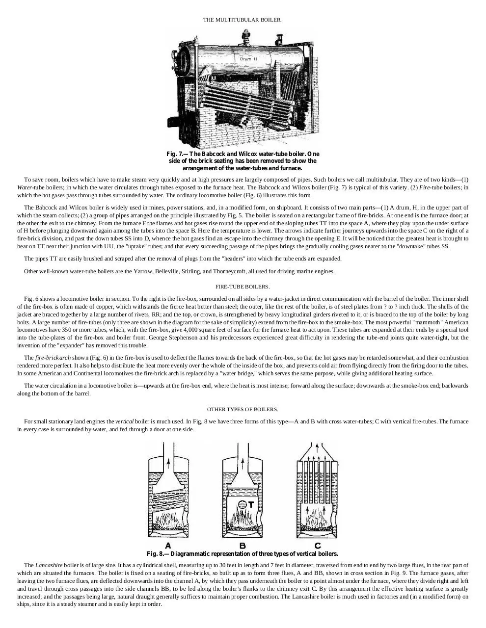
Fig. 7.—The Babcock and Wilcox water-tube boiler. One
side of the brick seating has been removed to show the
arrangement of the water-tubes and furnace.
To save room, boilers which have to make steam very quickly and at high pressures are largely composed of pipes. Such boilers we call multitubular. They are of two kinds—(1)
Water-tube boilers; in which the water circulates through tubes exposed to the furnace heat. The Babcock and Wilcox boiler (Fig. 7) is typical of this variety. (2) Fire-tube boilers; in
which the hot gases pass through tubes surrounded by water. The ordinary locomotive boiler (Fig. 6) illustrates this form.
The Babcock and Wilcox boiler is widely used in mines, power stations, and, in a modified form, on shipboard. It consists of two main parts—(1) A drum, H, in the upper part of
which the steam collects; (2) a group of pipes arranged on the principle illustrated by Fig. 5. The boiler is seated on a rectangular frame of fire-bricks. At one end is the furnace door; at
the other the exit to the chimney. From the furnace F the flames and hot gases rise round the upper end of the sloping tubes TT into the space A, where they play upon the under surface
of H before plunging downward again among the tubes into the space B. Here the temperature is lower. The arrows indicate further journeys upwards into the space C on the right of a
fire-brick division, and past the down tubes SS into D, whence the hot gases find an escape into the chimney through the opening E. It will be noticed that the greatest heat is brought to
bear on TT near their junction with UU, the "uptake" tubes; and that every succeeding passage of the pipes brings the gradually cooling gases nearer to the "downtake" tubes SS.
The pipes TT are easily brushed and scraped after the removal of plugs from the "headers" into which the tube ends are expanded.
Other well-known water-tube boilers are the Yarrow, Belleville, Stirling, and Thorneycroft, all used for driving marine engines.
FIRE-TUBE BOILERS.
Fig. 6 shows a locomotive boiler in section. To the right is the fire-box, surrounded on all sides by a water-jacket in direct communication with the barrel of the boiler. The inner shell
of the fire-box is often made of copper, which withstands the fierce heat better than steel; the outer, like the rest of the boiler, is of steel plates from ? to ? inch thick. The shells of the
jacket are braced together by a large number of rivets, RR; and the top, or crown, is strengthened by heavy longitudinal girders riveted to it, or is braced to the top of the boiler by long
bolts. A large number of fire-tubes (only three are shown in the diagram for the sake of simplicity) extend from the fire-box to the smoke-box. The most powerful "mammoth" American
locomotives have 350 or more tubes, which, with the fire-box, give 4,000 square feet of surface for the furnace heat to act upon. These tubes are expanded at their ends by a special tool
into the tube-plates of the fire-box and boiler front. George Stephenson and his predecessors experienced great difficulty in rendering the tube-end joints quite water-tight, but the
invention of the "expander" has removed this trouble.
The fire-brick arch shown (Fig. 6) in the fire-box is used to deflect the flames towards the back of the fire-box, so that the hot gases may be retarded somewhat, and their combustion
rendered more perfect. It also helps to distribute the heat more evenly over the whole of the inside of the box, and prevents cold air from flying directly from the firing door to the tubes.
In some American and Continental locomotives the fire-brick arch is replaced by a "water bridge," which serves the same purpose, while giving additional heating surface.
The water circulation in a locomotive boiler is—upwards at the fire-box end, where the heat is most intense; forward along the surface; downwards at the smoke-box end; backwards
along the bottom of the barrel.
OTHER TYPES OF BOILERS.
For small stationary land engines the vertical boiler is much used. In Fig. 8 we have three forms of this type—A and B with cross water-tubes; C with vertical fire-tubes. The furnace
in every case is surrounded by water, and fed through a door at one side.
Fig. 8.—Diagrammatic representation of three types of vertical boilers.
The Lancashire boiler is of large size. It has a cylindrical shell, measuring up to 30 feet in length and 7 feet in diameter, traversed from end to end by two large flues, in the rear part of
which are situated the furnaces. The boiler is fixed on a seating of fire-bricks, so built up as to form three flues, A and BB, shown in cross section in Fig. 9. The furnace gases, after
leaving the two furnace flues, are deflected downwards into the channel A, by which they pass underneath the boiler to a point almost under the furnace, where they divide right and left
and travel through cross passages into the side channels BB, to be led along the boiler's flanks to the chimney exit C. By this arrangement the effective heating surface is greatly
increased; and the passages being large, natural draught generally suffices to maintain proper combustion. The Lancashire boiler is much used in factories and (in a modified form) on
ships, since it is a steady steamer and is easily kept in order.
Fig. 9.—Cross and longitudinal sections of a Lancashire boiler.
In marine boilers of cylindrical shape cross water-tubes and fire-tubes are often employed to increase the heating surface. Return tubes are also led through the water to the funnels,
situated at the same end as the furnace.
AIDS TO COMBUSTION.
We may now turn our attention more particularly to the chemical process called combustion, upon which a boiler depends for its heat. Ordinary steam coal contains about 85 per cent.
of carbon, 7 per cent. of oxygen, and 4 per cent. of hydrogen, besides traces of nitrogen and sulphur and a small incombustible residue. When the coal burns, the nitrogen is released and
passes away without combining with any of the other elements. The sulphur unites with hydrogen and forms sulphuretted hydrogen (also named sulphurous acid), which is injurious to
steel plates, and is largely responsible for the decay of tubes and funnels. More of the hydrogen unites with the oxygen as steam.
The most important element in coal is the carbon (known chemically by the symbol C). Its combination with oxygen, called combustion, is the act which heats the boiler. Only when
the carbon present has combined with the greatest possible amount of oxygen that it will take into partnership is the combustion complete and the full heat-value (fixed by scientific
experiment at 14,500 thermal units per pound of carbon) developed.
Now, carbon may unite with oxygen, atom for atom, and form carbon monoxide (CO); or in the proportion of one atom of carbon to two of oxygen, and form carbon dioxide (CO2).
The former gas is combustible—that is, will admit another atom of carbon to the molecule—but the latter is saturated with oxygen, and will not burn, or, to put it otherwise, is the product
of perfect combustion. A properly designed furnace, supplied with a due amount of air, will cause nearly all the carbon in the coal burnt to combine with the full amount of oxygen. On
the other hand, if the oxygen supply is inefficient, CO as well as CO2 will form, and there will be a heat loss, equal in extreme cases to two-thirds of the whole. It is therefore necessary
that a furnace which has to eat up fuel at a great pace should be artificially fed with air in the proportion of from 12 to 20 pounds of air for every pound of fuel. There are two methods of
creating a violent draught through the furnace. The first is—
The forced draught; very simply exemplified by the ordinary bellows used in every house. On a ship (Fig. 10) the principle is developed as follows:—The boilers are situated in a
compartment or compartments having no communication with the outer air, except for the passages down which air is forced by powerful fans at a pressure considerably greater than that
of the atmosphere. There is only one "way out"—namely, through the furnaceand tubes (or gas-ways) of the boiler, and the funnel. So through these it rushes, raising the fuel to white
heat. As may easily be imagined, the temperature of a stokehold, especially in the tropics, is far from pleasant. In the Red Sea the thermometer sometimes rises to 170° Fahrenheit or
more, and the poor stokers have a very bad time of it.
Fig. 10.—Sketch showing how the "forced draught" is produced in a
stokehold and how it affects the furnaces.
SCENE IN THE STOKEHOLD OF A BATTLE-SHIP.
The second system is that of the induced draught. Here air is sucked through the furnace by creating a vacuum in the funnel and in a chamber opening into it. Turning to Fig. 6, we
see a pipe through which the exhaust steam from the locomotive's cylinders is shot upwards into the funnel, in which, and in the smoke-box beneath it, a strong vacuum is formed while
the engine is running. Now, "nature abhors a vacuum," so air will get into the smoke-box if there be a way open. There is—through the air-doors at the bottom of the furnace, the
furnace itself, and the fire-tubes; and on the way oxygen combines with the carbon of the fuel, to form carbon dioxide. The power of the draught is so great that, as one often notices
when a train passes during the night, red-hot cinders, plucked from the fire-box, and dragged through the tubes, are hurled far into the air. It might be mentioned in parenthesis that the socalled "smoke" which pours from the funnel of a moving engine is mainly condensing steam. A steamship, on the other hand, belches smoke only from its funnels, as fresh water is far
too precious to waste as steam. We shall refer to this later on.
BOILER FITTINGS.
The most important fittings on a boiler are:—(1) the safety-valve; (2) the water-gauge; (3) the steam-gauge; (4) the mechanisms for feeding it with water.
THE SAFETY-VALVE.
Professor Thurston, an eminent authority on the steam-engine, has estimated that a plain cylindrical boiler carrying 100 lbs. pressure to the square inch contains sufficient stored
energy to project it into the air a vertical distance of 3? miles. In the case of a Lancashire boiler at equal pressure the distance would be 2? miles; of a locomotive boiler, at 125 lbs., 1?
miles; of a steam tubular boiler, at 75 lbs., 1 mile. According to the same writer, a cubic foot of heated water under a pressure of from 60 to 70 lbs. per square inch has about the same
energy as one pound of gunpowder.
Steam is a good servant, but a terrible master. It must be kept under strict control. However strong a boiler may be, it will burst if the steam pressure in it be raised to a certain point;
and some device must therefore be fitted on it which will give the steam free egress before that point is reached. A device of this kind is called a safety-valve. It usually blows off at less
than half the greatest pressure that the boiler has been proved by experiment to be capable of withstanding.
In principle the safety-valve denotes an orifice closed by an accurately-fitting plug, which is pressed against its seat on the boiler top by a weighted lever, or by a spring. As soon as
the steam pressure on the face of the plug exceeds the counteracting force of the weight or spring, the plug rises, and steam escapes until equilibrium of the opposing forces is restored.
On stationary engines a lever safety-valve is commonly employed (Fig. 11). The blowing-off point can be varied by shifting the weight along the arm so as to give it a greater or less
leverage. On locomotive and marine boilers, where shocks and movements have to be reckoned with, weights are replaced by springs, set to a certain tension, and locked up so that they
cannot be tampered with.
Fig. 11.—A Lever Safety-Valve. V, valve; S, seating; P, pin; L, lever; F,
fulcrum; W, weight. The figures indicate the positions at which the
weight should be placed for the valve to act when the pressure rises to
that number of pounds per square inch.
Boilers are tested by filling the boilers quite full and (1) by heating the water, which expands slightly, but with great pressure; (2) by forcing in additional water with a powerful pump.
In either case a rupture would not be attended by an explosion, as water is very inelastic.
The days when an engineer could "sit on the valves"—that is, screw them down—to obtain greater pressure, are now past, and with them a considerable proportion of the dangers of
high-pressure steam. The Factory Act of 1895, in force throughout the British Isles, provides that every boiler for generating steam in a factory or workshop where the Act applies must
have a proper safety-valve, steam-gauge, and water-gauge; and that boilers and fittings must be examined by a competent person at least once in every fourteen months. Neglect of these
provisions renders the owner of a boiler liable to heavy penalties if an explosion occurs.
One of the most disastrous explosions on record took place at the Redcar Iron Works, Yorkshire, in June 1895. In this case, twelve out of fifteen boilers ranged side by side burst,
through one proving too weak for its work. The flying fragments of this boiler, striking the sides of other boilers, exploded them, and so the damage was transmitted down the line.
Twenty men were killed and injured; while masses of metal, weighing several tons each, were hurled 250 yards, and caused widespread damage.
The following is taken from a journal, dated December 22, 1895: "Providence (Rhode Island).—A recent prophecy that a boiler would explode between December 16 and 24 in a
store has seriously affected the Christmas trade. Shoppers are incredibly nervous. One store advertises, 'No boilers are being used; lifts running electrically.' All stores have had their
boilers inspected."
THE WATER-GAUGE.
No fitting of a boiler is more important than the water-gauge, which shows the level at which the water stands. The engineer must continually consult his gauge, for if the water gets
too low, pipes and other surfaces exposed to the furnace flames may burn through, with disastrous results; while, on the other hand, too much water will cause bad steaming. A section
of an ordinary gauge is seen in Fig. 12. It consists of two parts, each furnished with a gland, G, to make a steam-tight joint round the glass tube, which is inserted through the hole
covered by the plug P1. The cocks T1 T2 are normally open, allowing the ingress of steam and water respectively to the tube. Cock T3 is kept closed unless for any reason it is necessary
to blow steam or water through the gauge. The holes C C can be cleaned out if the plugs P2 P3 are removed.
Fig. 12.—Section of a water-gauge.
Most gauges on high-pressure boilers have a thick glass screen in front, so that in the event of the tube breaking, the steam and water may not blow directly on to the attendants. A
further precaution is to include two ball-valves near the ends of the gauge-glass. Under ordinary conditions the balls lie in depressions clear of the ways; but when a rush of steam or
water occurs they are sucked into their seatings and block all egress.
On many boilers two water-gauges are fitted, since any gauge may work badly at times. The glasses are tested to a pressure of 3,000 lbs. or more to the square inch before use.
THE STEAM-GAUGE.
It is of the utmost importance that a person in charge of a boiler should know what pressure the steam has reached. Every boiler is therefore fitted with one steam-gauge; many with
two, lest one might be unreliable. There are two principal types of steam-gauge:—(1) The Bourdon; (2) the Schäffer-Budenberg. The principle of the Bourdon is illustrated by Fig. 13, in
which A is a piece of rubber tubing closed at one end, and at the other drawn over the nozzle of a cycle tyre inflator. If bent in a curve, as shown, the section of the tube is an oval. When
air is pumped in, the rubber walls endeavour to assume a circular section, because this shape encloses a larger area than an oval of equal circumference, and therefore makes room for a
larger volume of air. In doing so the tube straightens itself, and assumes the position indicated by the dotted lines. Hang an empty "inner tube" of a pneumatic tyre over a nail and inflate
it, and you will get a good illustration of the principle.
Fig. 13.—Showing the principle of the steam-gauge.
Fig. 14.—Bourdon steam-gauge. Part of dial removed to show
mechanism.
In Fig. 14 we have a Bourdon gauge, with part of the dial face broken away to show the internal mechanism. T is a flattened metal tube soldered at one end into a hollow casting, into
which screws a tap connected with the boiler. The other end (closed) is attached to a link, L, which works an arm of a quadrant rack, R, engaging with a small pinion, P, actuating the
pointer. As the steam pressure rises, the tube T moves its free end outwards towards the position shown by the dotted lines, and traverses the arm of the rack, so shifting the pointer round
the scale. As the pressure falls, the tube gradually returns to its zero position.
The Schäffer-Budenberg gauge depends for its action on the elasticity of a thin corrugated metal plate, on one side of which steam presses. As the plate bulges upwards it pushes up a
small rod resting on it, which operates a quadrant and rack similar to that of the Bourdon gauge.
THE WATER SUPPLY TO A BOILER.
The water inside a boiler is kept at a proper level by (1) pumps or (2) injectors. The former are most commonly used on stationary and marine boilers. As their mechanism is much the
same as that of ordinary force pumps, which will be described in a later chapter, we may pass at once to the injector, now almost universally used on locomotive, and sometimes on
stationary boilers. At first sight the injector is a mechanical paradox, since it employs the steam from a boiler to blow water into the boiler. In Fig. 15 we have an illustration of the
principle of an injector. Steam is led from the boiler through pipe A, which terminates in a nozzle surrounded by a cone, E, connected by the pipe B with the water tank. When steam is
turned on it rushes with immense velocity from the nozzle, and creates a partial vacuum in cone E, which soon fills with water. On meeting the water the steam condenses, but not before
it has imparted some of its velocity to the water, which thus gains sufficient momentum to force down the valve and find its way to the boiler. The overflow space O O between E and C
allows steam and water to escape until the water has gathered the requisite momentum.
Fig. 15.—Diagram illustrating the principle of a steam-injector.
Fig. 16.—The Giffard injector.
A form of injector very commonly used is Giffard's (Fig. 16). Steam is allowed to enter by screwing up the valve V. As it rushes through the nozzle of the cone A it takes up water
and projects it into the "mixing cone" B, which can be raised or lowered by the pinion D (worked by the hand-wheel wheel shown) so as to regulate the amount of water admitted to B.
At the centre of B is an aperture, O, communicating with the overflow. The water passes to the boiler through the valve on the left. It will be noticed that the cone A and the part of B
above the orifice O contract downward. This is to convert the pressure of the steam into velocity. Below O is a cone, the diameter of which increases downwards. Here the velocity of
the water is converted back into pressure in obedience to a well-known hydromechanic law.
An injector does not work well if the feed-water be too hot to condense the steam quickly; and it may be taken as a rule that the warmer the water, the smaller is the amount of it
injected by a given weight of steam. Some injectors have flap-valves covering the overflow orifice, to prevent air being sucked in and carried to the boiler.
When an injector receives a sudden shock, such as that produced by the passing of a locomotive over points, it is liable to "fly off"—that is, stop momentarily—and then send the
steam and water through the overflow. If this happens, both steam and water must be turned off, and the injector be restarted; unless it be of the self-starting variety, which automatically
controls the admission of water to the "mixing-cone," and allows the injector to "pick up" of itself.
For economy's sake part of the steam expelled from the cylinders of a locomotive is sometimes used to work an injector, which passes the water on, at a pressure of 70 lbs. to the
square inch, to a second injector operated by high-pressure steam coming direct from the boiler, which increases its velocity sufficiently to overcome the boiler pressure. In this case only
a fraction of the weight of high-pressure steam is required to inject a given weight of water, as compared with that used in a single-stage injector.
Chapter II.
THE CONVERSION OF HEAT ENERGY INTO MECHANICAL MOTION.
Reciprocating engines—Double-cylinder engines—The function of the fly-wheel—The cylinder—The slide-valve—The eccentric—"Lap" of the valve: expansion of steam—How the cut-off is
managed—Limit of expansive working—Compound engines—Arrangement of expansion engines—Compound locomotives—Reversing gears—"Linking-up"—Piston-valves—Speed
governors—Marine-speed governors—The condenser.
H
aving treated at some length the apparatus used for converting water into high-pressure steam, we may pass at once to a consideration of the mechanisms which convert the energy
of steam into mechanical motion, or work.
Steam-engines are of two kinds:—(1) reciprocating, employing cylinders and cranks; (2) rotary, called turbines.
RECIPROCATING ENGINES.
Fig. 17.—Sketch showing parts of a horizontal steam-engine.
Fig. 17 is a skeleton diagram of the simplest form of reciprocating engine. C is a cylinder to which steam is admitted through the steam-ways W W, first on one side of the piston P,
then on the other. The pressure on the piston pushes it along the cylinder, and the force is transmitted through the piston rod P R to the connecting rod C R, which causes the crank K to
revolve. At the point where the two rods meet there is a "crosshead," H, running to and fro in a guide to prevent the piston rod being broken or bent by the oblique thrusts and pulls
which it imparts through C R to the crank K. The latter is keyed to a shaft S carrying the fly-wheel, or, in the case of a locomotive, the driving-wheels. The crank shaft revolves in
bearings. The internal diameter of a cylinder is called its bore. The travel of the piston is called its stroke. The distance from the centre of the shaft to the centre of the crank pin is called
the crank's throw, which is half of the piston's stroke. An engine of this type is called double-acting, as the piston is pushed alternately backwards and forwards by the steam. When
piston rod, connecting rod, and crank lie in a straight line—that is, when the piston is fully out, or fully in—the crank is said to be at a "dead point;" for, were the crank turned to such a
position, the admission of steam would not produce motion, since the thrust or pull would be entirely absorbed by the bearings.
Fig. 18.—Sectional plan of a horizontal engine.
DOUBLE-CYLINDER ENGINES.
Fig. 19.
Fig. 20.
Locomotive, marine, and all other engines which must be started in any position have at least two cylinders, and as many cranks set at an angle to one another. Fig. 19 demonstrates
that when one crank, C1, of a double-cylinder engine is at a "dead point," the other, C2, has reached a position at which the piston exerts the maximum of turning power. In Fig. 20 each
crank is at 45° with the horizontal, and both pistons are able to do work. The power of one piston is constantly increasing while that of the other is decreasing. If single-action cylinders
are used, at least three of these are needed to produce a perpetual turning movement, independently of a fly-wheel.
THE FUNCTION OF THE FLY-WHEEL.
A fly-wheel acts as a reservoir of energy, to carry the crank of a single-cylinder engine past the "dead points." It is useful in all reciprocating engines to produce steady running, as a
heavy wheel acts as a drag on the effects of a sudden increase or decrease of steam pressure. In a pump, mangold-slicer, cake-crusher, or chaff-cutter, the fly-wheel helps the operator to
pass his dead points—that is, those parts of the circle described by the handle in which he can do little work.
THE CYLINDER.
Fig. 21.—Diagrammatic section of a cylinder and its slide-valve.
The cylinders of an engine take the place of the muscular system of the human body. In Fig. 21 we have a cylinder and its slide-valve shown in section. First of all, look at P, the
piston. Round it are white grooves, R R, in which rings are fitted to prevent the passage of steam past the piston. The rings are cut through at one point in their circumference, and
slightly opened, so that when in position they press all round against the walls of the cylinder. After a little use they "settle down to their work"—that is, wear to a true fit in the cylinder.
Each end of the cylinder is closed by a cover, one of which has a boss cast on it, pierced by a hole for the piston rod to work through. To prevent the escape of steam the boss is
hollowed out true to accommodate a gland, G1, which is threaded on the rod and screwed up against the boss; the internal space between them being filled with packing. Steam from the
boiler enters the steam-chest, and would have access to both sides of the piston simultaneously through the steam-ways, W W, were it not for the
SLIDE-VALVE,
a hollow box open at the bottom, and long enough for its edges to cover both steam-ways at once. Between W W is E, the passage for the exhaust steam to escape by. The edges of the
slide-valve are perfectly flat, as is the face over which the valve moves, so that no steam may pass under the edges. In our illustration the piston has just begun to move towards the right.
Steam enters by the left steam-way, which the valve is just commencing to uncover. As the piston moves, the valve moves in the same direction until the port is fully uncovered, when it
begins to move back again; and just before the piston has finished its stroke the steam-way on the right begins to open. The steam-way on the left is now in communication with the
exhaust port E, so that the steam that has done its duty is released and pressed from the cylinder by the piston. Reciprocation is this backward and forward motion of the piston: hence the
term "reciprocating" engines. The linear motion of the piston rod is converted into rotatory motion by the connecting rod and crank.
Fig. 22.—Perspective section of cylinder.
The use of a crank appears to be so obvious a method of producing this conversion that it is interesting to learn that, when James Watt produced his "rotative engine" in 1780 he was
unable to use the crank because it had already been patented by one Matthew Wasborough. Watt was not easily daunted, however, and within a twelvemonth had himself patented five
other devices for obtaining rotatory motion from a piston rod. Before passing on, it may be mentioned that Watt was the father of the modern—that is, the high-pressure—steam-engine;
and that, owing to the imperfection of the existing machinery, the difficulties he had to overcome were enormous. On one occasion he congratulated himself because one of his steamcylinders was only three-eighths of an inch out of truth in the bore. Nowadays a good firm would reject a cylinder 1⁄500 of an inch out of truth; and in small petrol-engines 1⁄5000 of an
inch is sometimes the greatest "limit of error" allowed.
Fig. 23.—The eccentric and its rod.
THE ECCENTRIC
is used to move the slide-valve to and fro over the steam ports (Fig. 23). It consists of three main parts—the sheave, or circular plate S, mounted on the crank shaft; and the two straps
which encircle it, and in which it revolves. To one strap is bolted the "big end" of the eccentric rod, which engages at its other end with the valve rod. The straps are semicircular and
held together by strong bolts, B B, passing through lugs, or thickenings at the ends of the semicircles. The sheave has a deep groove all round the edges, in which the straps ride. The
"eccentricity" or "throw" of an eccentric is the distance between C2, the centre of the shaft, and C1, the centre of the sheave. The throw must equal half of the distance which the slidevalve has to travel over the steam ports. A tapering steel wedge or key, K, sunk half in the eccentric and half in a slot in the shaft, holds the eccentric steady and prevents it slipping.
Some eccentric sheaves are made in two parts, bolted together, so that they may be removed easily without dismounting the shaft.
The eccentric is in principle nothing more than a crank pin so exaggerated as to be larger than the shaft of the crank. Its convenience lies in the fact that it may be mounted at any point
on a shaft, whereas a crank can be situated at an end only, if it is not actually a V-shaped bend in the shaft itself—in which case its position is of course permanent.
SETTING OF THE SLIDE-VALVE AND ECCENTRIC.
The subject of valve-setting is so extensive that a full exposition might weary the reader, even if space permitted its inclusion. But inasmuch as the effectiveness of a reciprocating
engine depends largely on the nature and arrangement of the valves, we will glance at some of the more elementary principles.
Fig. 24.
Fig. 25.
In Fig. 24 we see in section the slide-valve, the ports of the cylinder, and part of the piston. To the right are two lines at right angles—the thicker, C, representing the position of the
crank; the thinner, E, that of the eccentric. (The position of an eccentric is denoted diagrammatically by a line drawn from the centre of the crank shaft through the centre of the sheave.)
The edges of the valve are in this case only broad enough to just cover the ports—that is, they have no lap. The piston is about to commence its stroke towards the left; and the eccentric,
which is set at an angle of 90° in advance of the crank, is about to begin opening the left-hand port. By the time that C has got to the position originally occupied by E, E will be
horizontal (Fig. 25)—that is, the eccentric will have finished its stroke towards the left; and while C passes through the next right angle the valve will be closing the left port, which will
cease to admit steam when the piston has come to the end of its travel. The operation is repeated on the right-hand side while the piston returns.
Fig. 26.
It must be noticed here—(1) that steam is admitted at full pressure all through the stroke; (2) that admission begins and ends simultaneously with the stroke. Now, in actual practice it
is necessary to admit steam before the piston has ended its travel, so as to cushion the violence of the sudden change of direction of the piston, its rod, and other moving parts. To effect
this, the eccentric is set more than 90° in advance—that is, more than what the engineers call square. Fig. 26 shows such an arrangement. The angle between E and E1 is called the angle
of advance. Referring to the valve, you will see that it has opened an appreciable amount, though the piston has not yet started on its rightwards journey.
"LAP" OF THE VALVE—EXPANSION OF STEAM.
In the simple form of valve that appears in Fig. 24, the valve faces are just wide enough to cover the steam ports. If the eccentric is not square with the crank, the admission of steam
lasts until the very end of the stroke; if set a little in advance—that is, given lead—the steam is cut off before the piston has travelled quite along the cylinder, and readmitted before the
back stroke is accomplished. Even with this lead the working is very uneconomical, as the steam goes to the exhaust at practically the same pressure as that at which it entered the
cylinder. Its property of expansion has been neglected. But supposing that steam at 100 lbs. pressure were admitted till half-stroke, and then suddenly cut off, the expansive nature of the
steam would then continue to push the piston out until the pressure had decreased to 50 lbs. per square inch, at which pressure it would go to the exhaust. Now, observe that all the work
done by the steam after the cut-off is so much power saved. The average pressure on the piston is not so high as in the first case; still, from a given volume of 100 lbs. pressure steam we
get much more work.
HOW THE CUT-OFF IS MANAGED.
Fig. 27.—A slide-valve with "lap."
Fig. 28.
Look at Fig. 27. Here we have a slide-valve, with faces much wider than the steam ports. The parts marked black, P P, are those corresponding to the faces of the valves shown in
previous diagrams. The shaded parts, L L, are called the lap. By increasing the length of the lap we increase the range of expansive working. Fig. 28 shows the piston full to the left; the
valve is just on the point of opening to admit steam behind the piston. The eccentric has a throw equal to the breadth of a port + the lap of the valve. That this must be so is obvious from
a consideration of Fig. 27, where the valve is at its central position. Hence the very simple formula:—Travel of valve = 2 ? (lap + breadth of port). The path of the eccentric's centre
round the centre of the shaft is indicated by the usual dotted line (Fig. 28). You will notice that the "angle of advance," denoted by the arrow A, is now very considerable. By the time
that the crank C has assumed the position of the line S, the eccentric has passed its dead point, and the valve begins to travel backwards, eventually returning to the position shown in
Fig. 28, and cutting off the steam supply while the piston has still a considerable part of its stroke to make. The steam then begins to work expansively, and continues to do so until the
valve assumes the position shown in Fig. 27.
If the valve has to have "lead" to admit steam before the end of the stroke to the other side of the piston, the angle of advance must be increased, and the eccentric centre line would lie
on the line E2. Therefore—total angle of advance = angle for lap and angle for lead.
LIMIT OF EXPANSIVE WORKING.
Theoretically, by increasing the lap and cutting off the steam earlier and earlier in the stroke, we should economize our power more and more. But in practice a great difficulty is met
with—namely, that as the steam expands its temperature falls. If the cut-off occurs early, say at one-third stroke, the great expansion will reduce the temperature of the metal walls of the
cylinder to such an extent, that when the next spirt of steam enters from the other end a considerable proportion of the steam's energy will be lost by cooling. In such a case, the
difference in temperature between admitted steam and exhausted steam is too great for economy. Yet we want to utilize as much energy as possible. How are we to do it?
COMPOUND ENGINES.
In the year 1853, John Elder, founder of the shipping firm of Elder and Co., Glasgow, introduced the compound engine for use on ships. The steam, when exhausted from the highpressure cylinder, passed into another cylinder of equal stroke but larger diameter, where the expansion continued. In modern engines the expansion is extended to three and even four
stages, according to the boiler pressure; for it is a rule that the higher the initial pressure is, the larger is the number of stages of expansion consistent with economical working.
Fig. 29.—Sketch of the arrangement of a triple-expansion marine engine. No valve
gear or supports, etc., shown.
In Fig. 29 we have a triple-expansion marine engine. Steam enters the high-pressure cylinder at, say, 200 lbs. per square inch. It exhausts at 75 lbs. into the large pipe 2, and passes to
the intermediate cylinder, whence it is exhausted at 25 lbs. or so through pipe 3 to the low-pressure cylinder. Finally, it is ejected at about 8 lbs. per square inch to the condenser, and is
suddenly converted into water; an act which produces a vacuum, and diminishes the back-pressure of the exhaust from cylinder C. In fact, the condenser exerts a sucking power on the
exhaust side of C's piston.
ARRANGEMENT OF EXPANSION ENGINES.
In the illustration the cranks are set at angles of 120°, or a third of a circle, so that one or other is always at or near the position of maximum turning power. Where only two stages are
used the cylinders are often arranged tandem, both pistons having a common piston rod and crank. In order to get a constant turning movement they must be mounted separately, and
work cranks set at right angles to one another.
COMPOUND LOCOMOTIVES.
In 1876 Mr. A. Mallet introduced compounding in locomotives; and the practice has been largely adopted. The various types of "compounds" may be classified as follows:—(1) One
low-pressure and one high-pressure cylinder; (2) one high-pressure and two low-pressure; (3) one low-pressure and two high-pressure; (4) two high-pressure and two low-pressure. The
last class is very widely used in France, America, and Russia, and seems to give the best results. Where only two cylinders are used (and sometimes in the case of three and four), a valve
arrangement permits the admission of high-pressure steam to both high and low-pressure cylinders for starting a train, or moving it up heavy grades.
REVERSING GEARS.
Figs. 30, 31, 32.—Showing how a reversing gear alters the position of the
slide-valve.
The engines of a locomotive or steamship must be reversible—that is, when steam is admitted to the cylinders, the engineer must be able to so direct it through the steam-ways that the
cranks may turn in the desired direction. The commonest form of reversing device (invented by George Stephenson) is known as Stephenson's Link Gear. In Fig. 30 we have a
diagrammatic presentment of this gear. E1 and E2 are two eccentrics set square with the crank at opposite ends of a diameter. Their rods are connected to the ends of a link, L, which can
be raised and lowered by means of levers (not shown). B is a block which can partly revolve on a pin projecting from the valve rod, working through a guide, G. In Fig. 31 the link is
half raised, or in "mid-gear," as drivers say. Eccentric E1 has pushed the lower end of the link fully back; E2 has pulled it fully forward; and since any movement of the one eccentric is
counterbalanced by the opposite movement of the other, rotation of the eccentrics would not cause the valve to move at all, and no steam could be admitted to the cylinder.
Let us suppose that Fig. 30 denotes one cylinder, crank, rods, etc., of a locomotive. The crank has come to rest at its half-stroke; the reversing lever is at the mid-gear notch. If the
engineer desires to turn his cranks in an anti-clockwise direction, he raises the link, which brings the rod of E1 into line with the valve rod and presses the block backwards till the righthand port is uncovered (Fig. 31). If steam be now admitted, the piston will be pushed towards the left, and the engine will continue to run in an anti-clockwise direction. If, on the other
hand, he wants to run the engine the other way, he would drop the link, bringing the rod of E2 into line with the valve rod, and drawing V forward to uncover the rear port (Fig. 32). In
either case the eccentric working the end of the link remote from B has no effect, since it merely causes that end to describe arcs of circles of which B is the centre.
"LINKING UP."
If the link is only partly lowered or raised from the central position it still causes the engine to run accordingly, but the movement of the valve is decreased. When running at high
speed the engineer "links up" his reversing gear, causing his valves to cut off early in the stroke, and the steam to work more expansively than it could with the lever at full, or end, gear;
so that this device not only renders an engine reversible, but also gives the engineer an absolute command over the expansion ratio of the steam admitted to the cylinder, and furnishes a
method of cutting off the steam altogether. In Figs. 30, 31, 32, the valve has no lap and the eccentrics are set square. In actual practice the valve faces would have "lap" and the eccentric
"lead" to correspond; but for the sake of simplicity neither is shown.
OTHER GEARS.
In the Gooch gear for reversing locomotives the link does not shift, but the valve rod and its block is raised or lowered. The Allan gear is so arranged that when the link is raised the
block is lowered, and vice versâ. These are really only modifications of Stephenson's principle—namely, the employment of two eccentrics set at equal angles to and on opposite sides of
the crank. There are three other forms of link-reversing gear, and nearly a dozen types of radial reversing devices; but as we have already described the three most commonly used on
locomotives and ships, there is no need to give particulars of these.
Before the introduction of Stephenson's gear a single eccentric was used for each cylinder, and to reverse the engine this eccentric had to be loose on the axle. "A lever and gear
worked by a treadle on the footplate controlled the position of the eccentrics. When starting the engine, the driver put the eccentrics out of gear by the treadle; then, by means of a lever
he raised the small-ends of the eccentric rods, and, noting the position of the cranks, or, if more convenient, the balance weight in the wheels, he, by means of another handle, moved the
valves to open the necessary ports to steam and worked them by hand until the engine was moving; then, with the treadle, he threw the eccentrics over to engage the studs, at the same
time dropping the small-ends of the rods to engage pins upon the valve spindles, so that they continued to keep up the movement of the valve." One would imagine that in modern
shunting yards such a device would somewhat delay operations!
PISTON VALVES.
In marine engines, and on many locomotives and some stationary engines, the D-valve (shown in Figs. 30–32) is replaced by a piston valve, or circular valve, working up and down
in a tubular seating. It may best be described as a rod carrying two pistons which correspond to the faces of a D-valve. Instead of rectangular ports there are openings in the tube in
which the piston valve moves, communicating with the steam-ways into the cylinder and with the exhaust pipe. In the case of the D-valve the pressure above it is much greater than that
below, and considerable friction arises if the rubbing faces are not kept well lubricated. The piston valve gets over this difficulty, since such steam as may leak past it presses on its
circumference at all points equally.
SPEED GOVERNORS.
Fig. 33.—A speed governor.
Practically all engines except locomotives and those known as "donkey-engines"—used on cranes—are fitted with some device for keeping the rotatory speed of the crank constant
within very narrow limits. Perhaps you have seen a pair of balls moving round on a seating over the boiler of a threshing-engine. They form part of the "governor," or speed-controller,
shown in principle in Fig. 33. A belt driven by a pulley on the crank shaft turns a small pulley, P, at the foot of the governor. This transmits motion through two bevel-wheels, G, to a
vertical shaft, from the top of which hang two heavy balls on links, K K. Two more links, L L, connect the balls with a weight, W, which has a deep groove cut round it at the bottom.
When the shaft revolves, the balls fly outwards by centrifugal force, and as their velocity increases the quadrilateral figure contained by the four links expands laterally and shortens
vertically. The angles between K K and L L become less and less obtuse, and the weight W is drawn upwards, bringing with it the fork C of the rod A, which has ends engaging with
the groove. As C rises, the other end of the rod is depressed, and the rod B depresses rod O, which is attached to the spindle operating a sort of shutter in the steam-pipe. Consequently
the supply of steam is throttled more and more as the speed increases, until it has been so reduced that the engine slows, and the balls fall, opening the valve again. Fig. 34 shows the
valve fully closed. This form of governor was invented by James Watt. A spring is often used instead of a weight, and the governor is arranged horizontally so that it may be driven
direct from the crank shaft without the intervention of bevel gearing.
The Hartwell governor employs a link motion. You must here picture the balls raising and lowering the free end of the valve rod,
which carries a block moving in a link connected with the eccentric rod. The link is pivoted at the upper end, and the eccentric rod is
attached to the lower. When the engine is at rest the end of the valve rod and its block are dropped till in a line with the eccentric rod;
but when the machinery begins to work the block is gradually drawn up by the governor, diminishing the movement of the valve, and
so shortening the period of steam admission to the cylinder.
Governors are of special importance where the load of an engine is constantly varying, as in the case of a sawmill. A good governor
will limit variation of speed within two per cent.—that is, if the engine is set to run at 100 revolutions a minute, it will not allow it to
exceed 101 or fall below 99. In very high-speed engines the governing will prevent variation of less than one per cent., even when the
load is at one instant full on, and the next taken completely off.
MARINE GOVERNORS.
Fig. 34.
These must be more quick-acting than those used on engines provided with fly-wheels, which prevent very sudden variations of speed. The screw is light in proportion to the engine
power, and when it is suddenly raised from the water by the pitching of the vessel, the engine would race till the screw took the water again, unless some regulating mechanism were
provided. Many types of marine governors have been tried. The most successful seems to be one in which water is being constantly forced by a pump driven off the engine shaft into a
cylinder controlling a throttle-valve in the main steam-pipe. The water escapes through a leak, which is adjustable. As long as the speed of the engine is normal, the water escapes from
the cylinder as fast as it is pumped in, and no movement of the piston results; but when the screw begins to race, the pump overcomes the leak, and the piston is driven out, causing a
throttling of the steam supply.
CONDENSERS.
The condenser serves two purposes:—(1) It makes it possible to use the same water over and over again in the boilers. On the sea, where fresh water is not obtainable in large
quantities, this is a matter of the greatest importance. (2) It adds to the power of a compound engine by exerting a back pull on the piston of the low-pressure cylinder while the steam is
being exhausted.
Fig. 35 is a sectional illustration of a marine condenser. Steam enters the condenser through the large pipe E, and passes among a number of very thin copper tubes, through which seawater is kept circulating by a pump. The path of the water is shown by the featherless arrows. It comes from the pump through pipe A into the lower part of a large cap covering one end
of the condenser and divided transversely by a diaphragm, D. Passing through the pipes, it reaches the cap attached to the other end, and flows back through the upper tubes to the outlet
C. This arrangement ensures that, as the steam condenses, it shall meet colder and colder tubes, and finally be turned to water, which passes to the well through the outlet F. In some
condensers the positions of steam and water are reversed, steam going through the tubes outside which cold water circulates.
Fig. 35.—The marine condenser.
Large 10" X 13" Prints from Vintage Internet Patents
Printed on Parchment Paper
CD of Entire Patent Document Included
Toy Engines
Farm Engines
Industrial Engines
Locomotives
This eBook is copyrighted by Weeden Steam ™, exact copies may be made for distribution providing all links remain in place and are active.
Download SteamEngine
SteamEngine.pdf (PDF, 1.4 MB)
Download PDF
Share this file on social networks
Link to this page
Permanent link
Use the permanent link to the download page to share your document on Facebook, Twitter, LinkedIn, or directly with a contact by e-Mail, Messenger, Whatsapp, Line..
Short link
Use the short link to share your document on Twitter or by text message (SMS)
HTML Code
Copy the following HTML code to share your document on a Website or Blog
QR Code to this page

This file has been shared publicly by a user of PDF Archive.
Document ID: 0000067895.