AE61 0967 Saturn C 3 C 4 Nova (PDF)
File information
This PDF 1.6 document has been generated by Adobe Acrobat 7.1 / Adobe Acrobat 7.1 Paper Capture Plug-in, and has been sent on pdf-archive.com on 27/04/2013 at 06:35, from IP address 27.33.x.x.
The current document download page has been viewed 2375 times.
File size: 122.02 MB (753 pages).
Privacy: public file


File preview
u
Ш"
REPORT NO. AE61"0967
CLASSIFICATION CHANGE
TO "
UNCLASSIFIED
By authorit^of T . D .
A A
!
A study of
LARGE LAUNCH VEHICLE SYSTEM
j:
FOR A MANNED LUNAR LANDING PROGRAM If /',.
ч.'"""""
"
CONTRACT NO. NASw"327
Prepared for
OFFICE OF LAUNCH VEHICLE PROGRAMS
NASA HEADQUARTERS, WASHINGTON, D. C.
GIIIIIIIID
GENERAL DYNAMICS | ASTRONAUTICS
(NASA!CR!137319 ) Д STDDY OF LA2GE
LAUNCH VEHICLE SYSTEMS FOE A M A N N E D
LONAE LANDING PROGRAM (General
Dynamics/Astronautics)
357p
N74"7399 7
00/99
Unclas
37295
;
/о/ ^s"
\ S T U D Y ( > F LAKG1"; L A U N C H V E H I C L E S Y S T E M S
FUH A M A N N E D L U N A R L A N D I N G PKUGHAM
't No. \Eol"(.;,'iT
PIN .;i"77:>
Coniract NASu":i27
<> UcLober I 1 .H.I
Approved by
Preparcel by ]{. <f.
К. Е. II
"M. U. l i a r l o v .
Pvoiect Engineer
Apprcned
Program Direc"Lor
Approve,!
P. Warr..s
Chief of
Prc'limmarv
F. J. Dore
'Director
Ail\anced S\sien.s
\pprov
!. W. Wuhee
Vice President
Research and E
GENERAL. DYNAMICS I ASTRONAUTICS
CONVAIR"ASTRONAUTICS
AE61!Q9G7
9 October 1961
О
FOREWORD
This study was conducted by tho Advanced Systems Engineering Section of
General Dynamics/Astronautics for the Office of Launch Vehicle Programs
of the National Aeronautics and Space Administration Headquarters, Wash!
ington, D. C.
The study was conducted on a project basis with Lead
responsibility as follows:
К. Ё. Hogeland
Project Engineer
G. К. С. Campbell
Design Technical Direction
R. Benzwi
Solid Prope11ant Systems
R. Frayer
Mission Performance
D. L. Dudas
Flight Mechanics
C. С. Love, Jr.
Thermodynamics
J. Bertani
Weights
D. Ноете
Guidance and Electronics
R. Goldberg
Reliability
T. Fago
Schedules
I c Polhaums
Test Programs
C. R. Smith
Automatic Checkout
C. Perry
Economic Analysis
Major contributions to the study were made by Wm. Daly in rendezvous tech!
niques and D. J. Jones, Jr. as technical consultant and project engineer
for contributing studies.
Also, the Radio Corporation of America was a major contributor to this
study in the area of automatic checkout.
CONVAIR"ASTRONAUTIC S
AE61~09t>7
9 October
1961
TABLE OF CONTENTS
Page
Section
1
SCOPE
2
2Л
202
2,3
LAUNCH VEHICLE SUBSYSTEM
General
Structure
Functional Subsystems
3
INTEGRATED SYSTEMS ANALYSIS
3!1
4
(Deleted)
4!1
5
PERFORMANCE
5!1
6
AERODYNAMICS
6!1
7
HEAT PROTECTION SYSTEMS
7!1
8
STABILITY AND CONTROL
8!1
9
RKLI ABILITY
9!1
10
DEVELOPMENT
10!1
11
COST CONSIDERATIONS
Jl!1
12
WEI (HITS
12!1
13
CONCLUSIONS AND RECOMMENDATIONS
13!1
1!1
\
2!1
2!1
2!2
2!107
Appendix
A
GLNERAL CHARACTERISTICS OF CONTROL COMPUTER KOR RAPID
CHECKOUT OF MISSILES AND SPACE VLHICLES, AND SOME
DETAILS OF THE TESTS THEY PERFORM
В
THE RCA 110 AND ITS API LICATION TO THL SATURN PROGRAM
A!l
B!l
a/
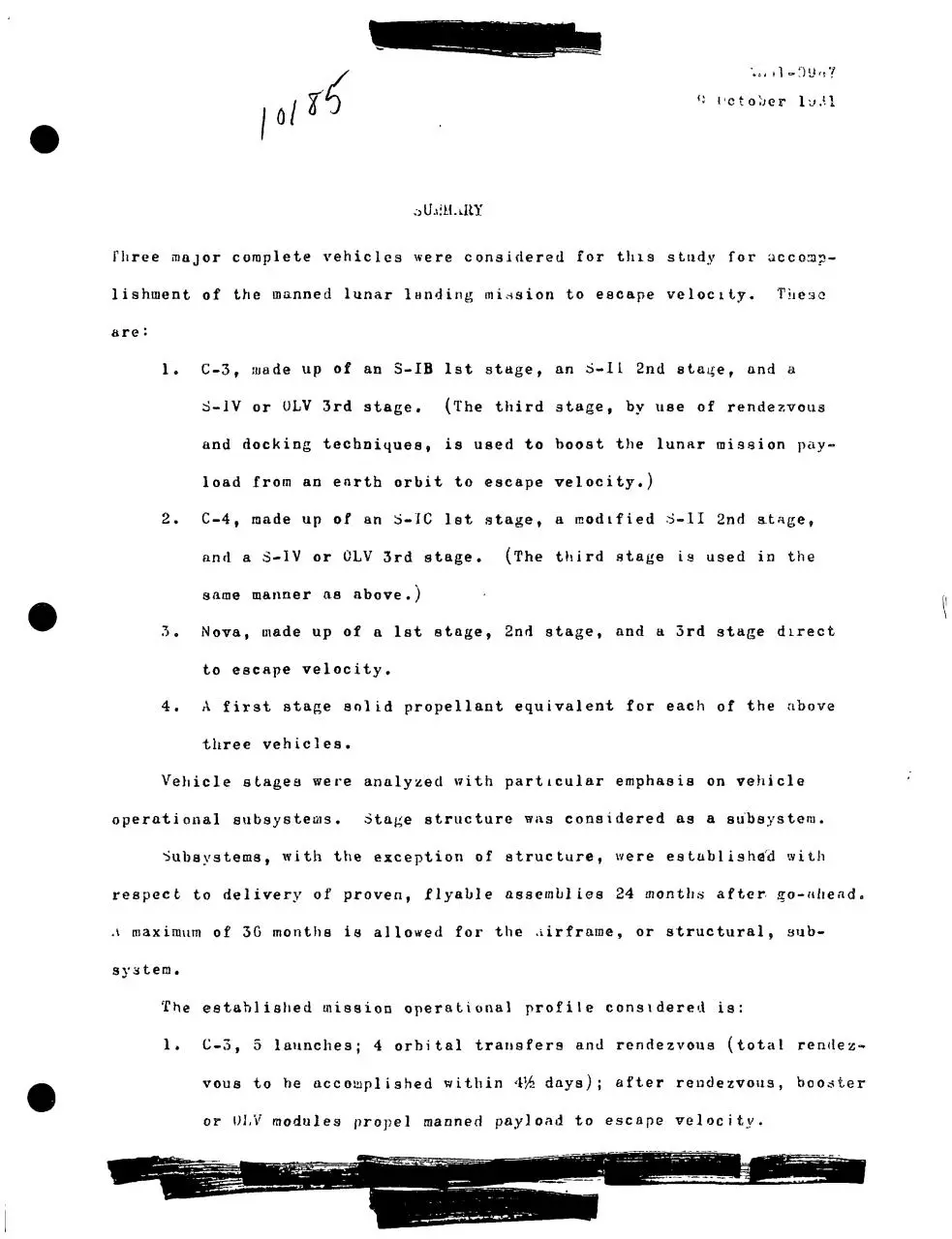
olh'M.LttY
Three major complete vehicles were considered for this study for accomp!
lishment of the manned lunar l a n d i ng mi!ssion to escape velocity.
These
are:
1.
C!3, made up of an 3!IB 1st stage, an S!1L 2nd staa;ef and а
S!1V or ULV 3rd stage.
(The third stage, by иве of rendezvous
and docking techniques, is used to boost the lunar mission pay!
load from an earth orbit to escape velocity.)
2.
C!4, made up of an S!IC let stage, a modified S!1I 2nd at«ge,
and a S!IV or OLV 3rd stage.
(The third stage is used in the
same manner as above.)
3.
Nova, made up of a 1st stage, 2nd stage, and a 3rd stage direct
to escape velocity.
4.
A first stage solid propellant equivalent for each of the above
three vehicles.
Vehicle stages were analyzed with particular emphasis on vehicle
operational subsystems.
Sta^e structure was considered as a subsystem.
Subsystems, with the exception of structure, were established with
respect to delivery of proven, flyable assemblies 24 months after jro!dhead.
л maximum of 3G months is allowed for the !iirframe, or structural, sub!
system.
The established mission operational profile considered is:
1.
C!3, 5 launches; 4 orbital transfers and rendezvous (total rendez!
vous to he accomplishe d within 4Ms days); after rendezvous, booster
or ULV modules propel manned payload to escape velocity.
Л '11!0067
9 ictober 1 У Ч 1
ii,
C!4,
2 launches; 1 rendezvous.
3.
Nova, straight shot to escape velocity.
UF ATTACK
The method of attack was to jjjirst establish c o m p o n e n t state of the art.
Presently
available proven components or components available as proven
items within a maximum of 12 months were checked against
profile.
the mission
Accuracy, reliability, weight, power requirements,
complexity of assembly were considered in the
and relative
evaluation.
Subsystems were synthesized from the component list, noting problem
areas in assuring compatibility, achieving a high confidence level, and
in improving subsystem
reliability and performance.
Alternates were evaluated by the following parameters,
listed, « ! fco define the best subsystem.
in the order
This included a cooperative effort
with reliability, cost, AGE, and weights engineering.
The parameters
used were:
1.
Reliability !! To include, where applicable, the c a p a b i l i t y for
in!orbi t checkout and repair.
2.
Accuracy !! To include the effect upon vehicle performance
weight of accuracy differences among alternate
3.
height —
subsystems.
To include the effect of weight differences
upon
payloed and rciasion reliability (as a function of launches per
m i n e ions) .
4.
Uase of Maintenance and Repair !! To include рге!launch activi!
ties on earth and in orbit, the enae of access for iuterchan'/e
9 October 1001
of components, the ease of performing such interchange, and tiie
ease of fault isolation from н central test point.
5.
Simplicity of Design !! To include interchangeability of components
and a minimum number of different items.
6.
Minimum New Development !! With reference to new principles rather
than to larger size in an existing component.
7.
Growth Potential
—
This refers to a design
in w h i c h improved
components can effect subsystem improvement va a design w h i c h
submits to no real improvement short of a new subsystem.
8.
Cost !! To include R & D first L/0 subsystems.
9.
Possibility of design for interchangeabi1ity of components with
similar components in other subsystems of overall launch vehicle.
SECONDARY I'ROPUJ.oION SYSTEMS
Systems considered:
1. Retro rockets.
2.
Ullage rockets.
3.
Pitch, yaw, and roll attitude control by means of:
(a) Solid!propellant motors,
(b) Bi!propellant (liquid) gas generator to motors,
(c) Ыопо!propellant l i q u i d direct to motor as applied to the
following stages where applicable:
(1) 1st stage —
HP!1 and LO .
(2) Upper stage !! LH
and
Ь0?.
(3) Hendezvous propulsio n unit, using l i q u i d storable p r o p e l !
1 ants .
I 1/
ui61"0!)0 7
0 O c t o b e r 1<(01
PitOPLJL.SlUN SUIVLY . l Y i T U M
Systems c o n s i d e r e d :
1.
1st
s t a g e "" KP"1 and L U , } ; t u r b o " p u m p type and b o o s t e r " p u m p
2.
U p p e r s t a g e s — L1I and LU ; t u r b o " p u r a p t y p e and b o o s t e r " p u r a p t y p e ,
3.
R e n d e z v o us
•1.
P r o p e l l e n t r o u t i n g and maximum u t i l i z a t i o n e f f e c t
propulsion — storable propellant; pressure"fed
(a) !Anti!vortex.
(b) Anti!pull!through.
(c) !Inti!slosli.
(d) Fine recirculation.
(e) Engine cool!down provisions.
PNEUMATICS
Systems considered:
1.
1st
s t a g e "" 11P"1 and 1Д) .
(a) Nitrogen (from LN0).
(b) Nitrogen for RP!1 and gaseous oxygen for LO .
(c) Helium.
(dj ПГ!1/LO
2.
gas generator for UP!1.
Upper stages LO
and LH9.
(a) Hydrogen b l e d for
L1I 0 .
(b) G0 2 for LO .
(c) Nitrogen (from LN ).
(d) Helium.
by:
type.
system.
fc!—^
f± f\ Й •
f>, ,!
f\ I
ЛЬ61!ОУГ) 7
0 Uctober 1061
3.
.Storable propellant rendezvous p r o p u l s i o n unit.
(a) Nitrogen (from LN ).
(b) Helium.
J'UUPELLANT U T I L I Z A T I O N
systems c o n s i d e r e d :
I.
Manometer.
2.
Transducer.
3.
Capacitor
probe.
Each of the above systems was investigated as to its a p p l i c a b i l i t y to:
1.
1st stages —
10
2. :Upper stages —
and UP!1.
LO
and LH .
3. "liendezvous propulsion unit !! liquid storables.
ENGINE GIMBAL ACTUATING SYSTEMS
oysteras considered:
1.
t
'Ilydraul ic oil.
2.
KP!1
3.
Cold gas cylindrica l or vane type actuators.
4.
Hot! gas vane type actuators.
fuel pressure
subsystem.
Each o'f the ^above aystein types was
1 .. 1st. stages !! LO
2!. ,' Upper stages —
'">.
investigated as to its a p p l i c a b i l i t y to:
and ПР!1 .
Ы>9
and Lfi .
Rendezvous p r o p u l s i o n unit !! l i q u i d a t o r a b l e s .
"""
3
0 October 1961
SECONDARY PLbVER
Systems to supply secondary power to each of the following stages as and
where applicable were investigated.
HP!1
The stages are:
1.
1st stage —
and LO .
2.
Upper stages —
3.
Rendezvous propulsion unit !! liquid storables.
LH
and LO .
Systems include:
1.
Batteries and fuel cells.
2.
Gas generators for use with hydraulics and alternators.
3.
Direct drive power unit off the main engines.
4.
Power distribution systems.
5.
Open!ог closed!cycle reciprocating engines.
6.
Fuel cells.
7.
Thermionic converters.
8.
Photo!missiori devices.
9.
Thermal storage.
10.
Open! or closed!cycle Mt)G converters.
11.
Open! or closed!cycle turbines.
THERMODYNAMICS
Л first approximation was made of base heating and flight aerodynamic
heating with respect to each configuration.
Structures and Performance.
Liaison was performed w i t h
.We I-0007
9 October 19Q1
AERODYNAMICS
Each configuration was given a first-approximation analysis to determine
air loads during the launch phase, including wind shear, and A and ft
effects.
Liaison was maintained w i t h structure, autopilot, and performance
areas.
WEIGHTS
A detailed weights breakdown was made for each design.
Subsystem weight
data was supplied early in the study to establish preliminary weights,
'••'eight data was kept current
throughout the study.
miFORilANCE
Based upon preliminary weights and dynamics data, the performance of
each configuration was evaluated and re-iterated as necessary to keep
the data current.
data.
Orbital assembly methods were based upon performance
J'aylond change data was circulated through subsystem design groups.
DYNAMICS
Based upon structure and weight preliminary data, a first-approximation
dynamic analysis was made to estimate bending frequencies and modes for
each configuration.
and
Liaison was maintained with structure, autopilot,
performance.
STRUCTURE
All stages were evaluated with respect to the following parameters:
1.
i>e ight.
2.
£ase of manufacture ( a i m p l i с ity) .
Coat.
bnvironmental conditions (acoustic, cryogenic, heating, etc.).
Minimum new development, testing, etc.
Interchangeabi1ity or use of common m a t e r i a l s or structural
parts (rings, stringers, skin, etc.) where p o s s i b l e .
LAUNCH HELKASIi
Establishment of the degree of the release problem, with respect
to vehicle design (T/W,
rigidity of structure, und related g
transients).
Analysis of known methods of ?nechanical restraint vs launch
vehicle design to determine release method offering high reliability at minimum vehicle structure weight increase.
HKNDU/VOUo EQUIPMENT
An analysis was made of small engine propulsion systems, including:
j 1.
i
• 2.
Cryogenic
. 3.
Solid propellants.
i
i
/
4.
L i q u i d storubles.
propellants.
M a i n propulsion and attitude control.
Uechnnieal
guidance was established for both closure phase and terminu-J
ducking of the rendezvous maneuver.
structural
,'
i
Analysis was made p r i m a r i l y on a
basis, considering:
1.
2.
3.
Tandem docking.
in-line docking.
Completel y automatic docking.
4.
'.an-in-systera docking.
AE01!0967
9 October 1961
GUIDANCE AND CONTROL
An analysis was made of possible operational methods for rendezvous and
assembly. Based upon reliability, least probable cost per mission and
resistance to interface and ECM, a pursuit!centered mode was selected. In this
mode, the first assembly element is pluced in a 300!n.mi. orbit. Subsequent
(pursuit) 'elements are placed in a compatible 100!n.rai. orbit. Each pursuit
element acquires the initial elementhnd performs an intercept!docking operation
using a self!contained automatic system. The manned element is the last to be
launched. Completion of each step in the orbital assembly sequence prior to
launch of the next assembly.
Having man on station in orbit throughout assembly does not seem to sig!
nificantly increase mission reliability. Highly reliable automatic systems
are possibje when modeled as growth versions of the present air intercept
guidance integrated with astro!inertial guidance systems. Docking can be
readily automated and, even with man in loop, requires extensive instru!
mentation n Man, on station in orbit, degrades mission effeciency by increas!
ing possibilities of a new being required to replace or resupply him as
\
time increases.
A study wfeis made of guidance and control requirements as related to
vehicle performance.
A parallel study of component performance available
for flight'teetung 24 months after go!ahead was accomplished, and component
;ierformance was found to be c o m p a t i b l e with m i s s v o n requirements.
type rc!cju Bremen 1\в wore estnbliahcri.
A paylcad!centralized system was
lected w i t h only''veetigal units in lower stages.
,.nd
Component
se!
A recommended rendezvous
docking system using HF only «s presented in some detail.
Astro!inertial
A..G 1!0967
9 October 19G1
guidance is not discussed in detail, since this subject i.s e x t e n s i v e l y
treated in recent studies.
TELEilETHY
The available types of telemetry systems were investigated, and their per!
formance was compared to the Saturn system requirements.
Selections and
recommendations were made, based on flexibility, weight, reliability, and
the ability to standardize on a common type for all stages.
AUTOMATIC CHECKOUT
Л highly reliable ground c/o automated system was investigated.
Liaison
was maintained with all vehicle subsystems to verify c o m p a t i b i l i t y .
Fast,
complete, and non!ambiguous go!no go .system tests; and reasonably fast fault
isolation were priffle considerations.
Special attention was given to automatic checkout equipment that must
be carried to orbital rendezvous.
T h i s equipment w i l l be used i m m e d i a t e l y
prior to and after terminal docking rendezvous is completed,
RANGE .SAFETY AND ЛВОПТ 1N3TUMENTAT' ON
This subject was discussed w i t h respect to a manned payload.
The following
systems were established for aborts over the entire mission profile:
1.
Abort sensing.
2.
Abort logic
3.
Abort procedure control:
(decision).
Separation of manned module, Direct
return vs orbit pnth control modes, and Destruction of v e h i c l e
stages by ground or capsule command.
AE61!0967
9 October 1961
APPENDIX A
GENERAL CHARACTERISTICS OF CONTROL COMPUTER FOR RAPID CHECKOUT OF
MISSILES AND SPACE VEHICLES AND SOME DETAILS OF ТЛЕ TESTS THEY PERFORM
A 1/ CONTROL COMPUTER CAPABILITIES AND CHARACTERISTICS
The utilization
of automatic digital checkout techniques allows a compression
of the time required for launch checkout, and therefore, an increase in the
allowable launch rate for a given launch facility.
A 1.1
ON!LINE OPERATION
Such an automatic checkout system is designed around a high!speed, digital
computer capable of real!time monitoring and testing of hundreds of analog,
digital and discrete functions.
The automatic checkout system relieves the
launch personnel of the manual checkout and countdown tasks, but still
enables full control to be in the hands of the supervisory personnel.
Fast,
repeatable self!checks are available utilizing electronic fast access
memories; fault location sub!routines may be preprogrammed and called upon
automatically on a priority basis to prevent operation delay; expandability
and flexibility are built into the design by means of modularization and
advanced techniques for easy programing.
A 1.2
COMPUTER CONTROLLED CHKCKOUT SYSTEM
AE61!0967
9 October 1961
FigureЛ1.2!1 shows the basic components needed in an Automatic Integrated
checkout and launch control system.
At the left of the figure is the
control computer and its peripheral gear.
This consists of the necessary
tape stations for program storage, etc., a control and display console,
and the flexowriter paper punch and reader for input preparation.
The
flexowriter is also used for automatic printout of any information it is
desired to print.
The input registers bring the input information (replies,
discreets, etc.) in from specific addresses and feeds it to the computer
for processing.
The output registers send out the commands, stimuli,
interrogations, etc., to specific addresses in the equipment being tested.
Al.2.1
SIGNAL FLOW IN AUTOMATED CHECKOUT SYSTEM !! The computer program
output is digital in form and can be sent directly to the address register,
the commend register, and/or the control register (See FigureA102!2)0
These
registers can be remotcd to the pad via the digital data link without
interfering with the normal operation of the digital computer.
The
replies from the pad equipment in many cases will be analog in form and
will have to be converted to digital form for transmission back to the
computer.
Nearly all the information going either direction can be digitized.
This reduces the complication of analog transmission lines especially if
the blockhouse!to!pad
distance becomes a mile or more.
Reference to
FigureAl.2!2.makes visualization of the operation much easier.
A command
or a control signal (a computer word) goes out on the output bus to the
proper register on the pad via the digital data link.
Its address goes
out to the address register at the sume time.
4!?,
"l".я'
Ч" °
""J
Г5 II • «
V
•v '• "v
•
"
•
•
Й. u
vf"'s
о з
J
>5 О
ез
с в се с
о
"но
U
Qu
"с ^ о
•*"> с о. со
о
Subsystem s
Prop. Load
Gnd. P w r .
Hydraulicj
Pneumatics
Я "Н
"I •*
•л
>}
ел
S
о
(J
"а
3
О
_£
U
1)
j;
и
я
"з
о
"("1
(ц
Ы)
0)
и
f>
•rl
a
to
eh
и
3
tc
3
"\
V
•• i
Ч
— —
—
' »•
P 'i
<
f — •:.
— " f.
~
С
X
Э
3
'"' ~
'— "Л
"
J
^
5
i
D
V
^" О
i :• I /—J
i
i
" <с
c*
^ 5
**'
0
з^
х. ,
\
";
^
H
1
"^k"
5 "ч"
_ ~ ~
>
^
'
\
~ ' '
~ _
—.
' "'
•< ""
~ .<
t:: ;<"
"^
""
5
— и
X.
^ i:
„! ^,
tv. Jl,
", '"i
"J X
x
U X.
u i
J
Л"4
AE61-0967
9 October 1961
If the command calls for a voltage, the appropriate generator is
switched in and, by means of the address control, it is directed to the
proper input test point in the vehicle.
The reply from the vehicle appears
on the corresponding output test point and, by means of the address register,
information goes to the analog distributor, the analog multiplexer, the
analog-to-digital converter, and then via the digital data link back to
the computer for evaluation and appropriate action.
In the discrete command and response area many separate discretes can
be packed simultaneously into one computer word length.
For example, if the
standard word length of the computer used is 30 binary bits, each bit can
represent a separate discrete (on-off) signal.
The external input-output register addressing capability should be
flexible to such an extent that additional control channels can be added
simply by implementing additional registers.
The computer's high-speed core
memory will be of sufficient size (i.e., 2000 to 4000 words) to store entire
vehicle package test routines. 'This avoids paying frequent access-time
penalties required when bring in portions of test routines from drum
(milliseconds) or tape station (minutes) bulk memories.
However, drum
storage "(4000 to 40,000 words plus buffer tracks) and tupe stations
(approximately 100,000 words each) are required for economical bulk
of checkout and launch control programs.
The computer via a complete instruction complement offers a full
general-purpose calculation and data-processing capability»
.4=5
ЛЕ61!0967
9 October 1961
APPENDIX В
В 1/ THE RCA 110 AND ITS APPLICATION TO THE SATURN PROGRAM
The advent of programs to launch large space vehicles intended to rendezvous
with other vehicles in space or to reach the Moon or Mars or Venus is
placing ever increasing importance on the requirements for real!time
control and on!line dnta reduction capabilities of the ground checkout
equipment.
The success of these programs, and the lives of raen, will
depend upon the capability of maintaining carefully predetermined launch
schedules while retaining a high degree of confidence in checkout and
launch sequencing methods.
Thus, the requirements aie increasing for
speed, programming flexibility, precision, and reliable performance of
checkout equipment and procedures.
This points the way inevitably to
the need for automatic checkout equipment and, further, to internally
programmed high speed machines.
The only machines currently available
to meet requirements are high speed general purpose digital computers.
One computer system was designed especially to meet the requirements
of real!time control in industrial processes and is well suited to perform
both launch control and checkout operations in real!time.
Being an
existing off!the!shelf item with known characteristics that satisfy Saturn
system demands, it was used as the heart of the automatic test equipment
set forth in this study»
It has the necessary speed, programming flexi!
bility, reliability, and precision to suit the needs of an internally
programmed automatic checkout system for large space vehicles.
FigurtAl.2!1
is и typical block diagram of a computer controlled integrated checkout
—^^Ц^*",__;>
1• . "
ryt^s ш"Зс"а * 8 2""';<"
and launch control system for space vehicleso
AE61"0967
9 October 1961
Following are some of the
specifications which illustrate the capabilities of the computer system
in this application.
Bid
SPEED
This computer has a 9.7 microsecond memory cycle and 29 microsecond word
time (including access) enabling it to do all calculations and make control
decisions as fast as test conditions change, or in real!time, for hundreds
of data channels and control loops.
It can add or make a decision in
58 microseconds (including access time), or at a rate of 17,240 operations
per secondo
It can scan analog signals and compare them against high and
low limits at a rate of 2,200 points per second, scan incoming discretes
at a rate of 60,000 points per second, or can address, monitor analyze
and control digital or analog information at a rate of 3,OOO points per
second.
Even the access time to the drum memory, a slow 8.3 milliseconds
'average as compared to the 3.5 microsecond access time to the high speed
core memory, is short enough to permit an average testing rate of nearly
12O decisions per second, more than an order of magnitude higher rate
than the average testing rate expected of large space vehicles.
Normally,
however, block transfer of data from drum memory is employed, which allows
the computer to keep up with even the fastest vehicle and GSE processes,
such as telemetry and airborne guidance.
B!2
АЁ61!0967
9 October 1961
В1.2
PROGRAMMING FLEXIBILITY
Programming flexibility depends upon the size of the computer memory and
upon the ea&e with which program changes up to 4,096 words (even more by
adding external storage), enough to accommodate entire vehicle package
i
test routines, including call!up of special subroutines on the occurrence
of uialfunctionso
The magnetic drum bulk storage may contain up to 16,384
words on standard size drums, or more by adding drums, sufficient to
accommodate entire vehicle checkout programs.
Though not recommended as a
means of programming test routines, a local maintenance and control panel ie
available which allows the programmer to cause the computer to step through
a program manually and enables the programmer
to make on!the!spot changes
to program subroutines, as an aid to program development and verification
in early R/D phases.
В 1.3
RELIABILITY
The reliability of this computer controlled checkout system is enhanced
by the use of circuits and design concepts already proven in tens!of!
thousands of hours of operation.
Bugged construction and gasketing
further enhance the computer's capacity to resist detrimental effects of
extreme environmental conditions.
B1.4
PRECISION
The maximum accuracy of any computer, without special programming, is a
function of itto word length.
The 24!bit word length of this computer
B=3
AE61!0967
9 October 1961
yields a maximum accuracy better than one part in eight million.
Therefore,
data degradation due to round!off or truncation errors is avoided, and the
"double!precision
arithmetic" often encountered in machines with inadequate
word length is not required.
On the other hand, double precision arith!
metic can be used to yield a resolution of one part in 7!к 10
,
In addition to the specifications discussed above, the machine has
certain features that materially enhance its capability to function
effectively ая a control computer for automatic checkout systems.
Some
of the more significant features are as follows:
lo
Л non!volatile memory enables the computer to store automatically
the contents of till registers and the arithmetic units in the
core memory in the event of a power failure.
The computer is
thus ready to resume the interrupted operation upon the reappli!
cation of normal power.
Or, if desired, the computer can incor!
porate the capability to switch automatically to an alternate
power source.
2.
Automatic priority interrupt allows the computer to interrupt a
current program to accept a program of higher priority, automati!
cally store the contents of all registers, and then return
automatically to the same points in the interrupted program and
resume the interrupted operations.
Multiple priority interrupts
can occur, causing the computer to step up through several levels
of priority and back down again to the program originally inter!
rupted, permitting each incomplete program to be finished when
time is available.
AE61!0967
' 9 October 1961
3o
Automatic self checking can be programmed to occur whenever
computer time IB available, on, a low priority level.
4.
Buffering self checking can be programmed to occur whenever
computer time is available, on u low priority level.
5»
The computer can be programmed to switch to alternate programs or
take other emergency steps upon the occurrence of parity, over!
flow, or instruction code alarms so that control will not be lost
while the condition is being corrected.
6«
An inoperable output device causes the computer to signal the
operator, store the information for printout later, and move on
to other tasks until the output device is operable again.
7о
The validity of all data transferred between drum memory, core
memory, and the arithmetic unit is verified by making parity
checks.
The address of an instruction causing a parity error
is automatically stored to aid the operator in finding the trouble
quickly»
80
The computer (See FigA/,..^!2!)has many memory size options and
highly flexible input/output configurations ahich can be tailored
to fit many different applications.
This can Lie done eqeily and
economically through the use of modular design techniques and
utilization of "off!the!shelf" hardware.
The use of a digital computer in the airborne guidance package of the
Saturn vehicle has dictated the use of general purpose digital computers
to perform checkout and control functions, to obtain compatibility both of
speed of operation and of data format.
The computer system described above
is the ГССЛ 110 and it was chosen because it meets these requirements,
AE61~O967
9 October 1961
provides the capability of performing типу additional test ьш! control
functions, and can be easily expanded to iiieet further Saturn program
requirements as they arise.
As supplied the computer incorporates two
additional cabinets containing input/output signal conditioning equipment
to handle COO analog signal inputs, 250 discrete signal outputs and 250
discrete signal inputs.
The computer complex is capable, then, of real!
time monitoring and control of hundreds of analog and discrete signals.
The input/output register addressing capability is sufficiently flexible!
to allow implementation of additional control and monitoring channels by
simply adding more registers.
The computer complex can then communicate
with the airborne guidance, verify the operability of all telemetry channels,
control and monitor fueling operations, and perform many other functions,
including self!checking.
B!6
AE61!0967
9 October
В 2/
1961
SUBSYSTEM CHECKOUT TESTS
In the following paragraphs, subsystems tests performed by the control
computer are described.
These tests cover the propulsion subsystem, the
electrical networks, RF tests, guidance and control functions and the
telemetrv systems.
В 2.1
PROPULSION SUBSYSTEM
When the vehicle is placed upon the pad, it receives a complete checkout,
systems check, and simulated flight test.
Dry checkout of the propulsion
equipments will be somewhat detailed in the assembly area but will not be
as complex as the tests performed at the factory.
This minimizes the time
spent on the pad as the actual propulsion system pre!launch check need
be only on a survey basis.
The major vehicle propulsion
functions and equipment which require
checkout are:
Pneumatic Control
Propulsion System Electrical Control
Electrical Heaters and Pressure Switches
Pneumatic System
Propellent Tanks Pressurizing
Hydrogen Tanks
LOX tanks
Engines
Engines Start and Cut!Off Sequencing
AE61"096 7
9 October
Since the propulsion
equipments are subjected
1961
to a high!level checkout
before arriving at the assembly area, it ie not required that all test
points and pressure
assembly.
taps be accessible for checkout during vertical
Therefore, components will be pressurized
and activated to
simulate only рге!launch loading and pressuriz.ation; equipment responses
to stimuli and leakages wilJ be determined by automatic checkout equipment
except when established as
impractical.
No additional fixtures or equipment arc required to be installed
within the vehicle and no disconnection and reconnection of vehicle
fittings are required other than that required at transfer points.
All
switching to specific circuits is done by switching unite and all "T"
connections are removed when tests are completed.
Any required flexibility
of the automatic checkout equipment to provide checkout of various stages
and equipments is available.
A majority of the tests to be performed for checkout of the propulsion
equipments are of the following types:
Continuity tests of electrical circuitry
Measurement tests of contact and insulation resistance
Verification tests of solenoid and valve activation
Determination tests of leakage and/or rates of leakage
Time!rate!measurement
tests of component
activation
Thermal!measuremen t tests smd response rate of thermal!control tests
Measurement tests of pull!in/drop!out
voltages and current drain during
component activation.
Q»8
I
ЛЕ61!096
?
9 October 1961
Checking of valves, pneum.itдс and hydraulic elements, and other
mechanical devices of the vehicle is not automated as easily as is the
checking of electrical items.
Control of exact pressures by external
automatic devices is possible but difficult.
It is possible to automatic!
ally test most equipments, but analysis indicates that in some areas Lt
ma!y be prohibitively difficult.
Leakage tests are made on the assembled vehicle after a pressure is
applied.
Depending on the leak rate permissible,
the accessibility of
components and the availability of measuring devices, these tests can be
performed in the following manner:
(1) audible, where a discernible leak
is hissing (hard to automate); (2) manually, where a leak detecting
solution or a gas!tracer
instrument can be applied near critical joints
and fittings und an estimation can he made of leakage rate and compared
to allowable limits (also hard to automate); (3) automatically, where
transducera can be monitored for initial pressure, after charging with
gas, nnd finn] pressure, after a specific length of time, with these
readings compared automatically to determine the leakage rate (digital
transducers have an application in this checkout area); and ^4)
automatically, by the use of n suiffer(e) and nn active changing gas,
such as helium, connected to a sensitive analyzer equipped with an alarm
mechanism.
Engine valve sequencing and timing can be monitored in the assembled
vehicle from established monitoring points both at the hangar vertical
assembly area and at the launch site.
Actual timing and sequential
order
of the valves can be determined and verified automatically by the checkout
equipment.
B!9
AE61=0967
9 October
1961
The automatic checkout equipment, by the application of discrete
commands and the verification of the response stimuli, can perform all
required electrical checks.
Pressure switches can be stimulated pneumat!
ically and checked; the activation of check valves, relief valves, etc.,
can be verified; electrical continuity of circuits can be checked; the
operation of electrical heaters can be verified (thermally by the use
of digital transducers); and contact and insulation resistance limits can
be verified.
В2.2
ELECTRICAL NETWORKS
Ih general, an electric and/or electronic network consists of the necessary
circuits in both the vehicle and the Ground Support Equipment (GSE)
to:
(l) allow remote operation of the vehicle's electrical and electronic
components (.such as attitude control, RF transmitters and receivers and
flight instrumentation) ; (2) to sequence «.!heckout and monitoring equipment;
and ^3) to perform рге!launch monitoring (such as activating displays,
showing flight programming, vehicle conditions, etc.).
All general network components such us relays, resistors, diodes,
and timers one installed in vehicle distributors and ground relay racks.
The required vehicle distributors are power, control, propulsion, and
measuring networks.
These components, in addition to vehicle cable ..
harnesses, ground cables, power sources, and firing and monitor panels,
comprise the general network system.
In the vertical checkout are.!i, systems tests on the vehicle networks
are carried out by stimulating the vehicle from controlled stimuli
sources
8=10
AE61!0967
9 October 1961
and/or from controlled stimulators.
These tests check many of the vehicle
components in addition to the cabling itself.
The<checkout control computer,
under ргорг.чп» control, chooses t(>e test circuit (switching) and the stimuli
for the function checked (such ns insulation resistance, continuity,
voltage, polnrity, etc.), evaluates the replies from the network, and
feeds the inform.!ition to the recorder or printer for permanent record.
The recordings taken at succeeding times can be compared to determine
if any drifts have occurred.
This test will provide checks for the
existance of factors such ns distortion, cross!talk, leakage, improper
impedance levels, system interference, etc0
Most of the vehicle measure!
ments are designed nnd conditioned to produce calibrated outputs in the
0 to 5 volt range.
tl!e ground.
Many of the on!board measurements are telemetered to
In addition in checkout, some of the on!board
measurements
con he sent by "hard wireH'(n physical connection) to the ground equipment
for comparison and recordingo
If it is planned to use these hard wire
connections, the vehicle dosipn should include their installation for easy
access from the outside.
The switching between hard!wire
transmission
and telemetry can be accomplished by the use of "T" relays. tthen the
relays are energized, the measurements go to the telemeter and, when they
are de!energized, the measurement signals proceed to the ground equipment
by hard wire.
В 2.3
RF TESTS
Application of the Automatic Checkout Equipment to the RF tests of the
vei'icle and the GSE is divided into the following sections:
eocaand1 system
AE61!0967
9 October 1961
tests and radar beacon tests.
The feasibility of automating telemetry HF
tests is discussed under a separate heading entitled "Telemetry Systems".
В 2.3.1
COMMAND SYSTEM TESTS —
The command receivers translate the destruct,
cutoff, and other functions to the vehicle after transmission from the
ground.
The receiver portion of this unit contains an audio decoder which
is a logic element to channelize intelligence.
The outputs of this audio
decoder cause relay closures which actuate the proper vehicle subassemblies.
The following tests will be conducted on the command receivers; cutoff,
overall systems and KF compatibility.
The engine cutoff test evaluates the important ON/OFF function by
measuring contact resistance sensitivity and drift of relay pull!in and
dropout, and relay coil current.
For the overall systems test, with receivers installed in the vehicle,
the command system will be exercised to monitor installation procedures.
This test will include the monitoring of subsystem response to commands
such as certain mechanical actuators.
When all radiative assemblies have been installed in the vehicle, RF
and compatibility tests are performed.
Each KF system is energized
sequentially, then simultaneously, together with ground transmitters and
with vehicle antennas in place.
The command receiver AGC voltages would
then indicate the presence of interference.
The interaction of these
receivers with telemetry, guidance and control, and destruct systems
would be further analyzed at this time.
B2.3.2
RADAR BEACON TESTS —
A radar beacon operating in C!band or S!4)and
may be carried on board the vehicle to present a very clear target to
tracking radar(s).
The tests to be performed on!these beacons to insure
.>
B~12
AE61!0967
9 October 1961
mission reliability of these transponders are:
RF compatibility test
discussed above, a sensitivity test, ami simulated flight test.
The transponder triggering sensitivity is measured by decreasing the
signal!generator output nnd determining that threshold level of signal which
will cause a response for each interrogation.
Receiver МмС will be measured
and evaluated at this time to determine receiver sensitivity.
Minimum
discernible signal and tangential sensitivity will also be measured.
DC voltages from the power supply as well as AGC voltage will be
digitized for accurate measurement by the checkout data processor.
In the simulated flight test, umbilicals will have been disconnected
and vehicle radiative systems energized.
The beacon tests to be performed
at this time are more qualitative in nature.
Interrogation pulses will be
gradually diminished corresponding to flight with AGC and pulse response
modified via the telemetry and checkout equipment respectively.
В 2„4
GUIDANCE AND CONTROL
For the purpose of this study, the guidance and control package will be
considered as a separate assembly since it will,probably be located above
the uppermost stage and may separate with the payload to supply orbital
attitude control.
However, it is assumed that the flight control (or
autopilot computer) amplifiers that drive the hydraulic
engine!gimballing
actuators, or the proportional liquid injection valves of the obliquo
Shockwave type of thrust vector control, in each stage are located in their
respective stages.
B!13
ЛЕ61~096
7
9 October 1961
The guidance and control package, because it is almost completely
electronic in nature, is rapidly adaptable to automatic checkout.
ti
FigureB2.4!l is a block diagram illustrating the major subassemblies of
the full inertial guidance and control package and the type of stimulus
source!response measurement loops required in the automatic checkout system
to communicate with and to checkout the guidance and control package.
The major subassemblies of the guidance and control are as follows:
the
flight sequencer, stable platform, flight!control computer, digital
guidance computer, and telemetry system.
В 2.4.1
FLIGHT SEQUENCE —
This is a relay!counting
chain which receives its
inputs from the flight program stored in the drum of the airborne computer
and which generates timed discrete commands in the proper sequence as
required by the vehicle equipment.
B2.4.2
STABLE PLATFORM —
The stable platform provides a fixed angular
reference in inertial space.
Three gyros mounted with their sensitive
axes parallel to thevpitch, yaw, and roll axes of the vehicle provide
platform stabilization.
Three integrating accelerometers, mounted on the
platform, measure vehicle accelerations along the slant rungi;, Blunt!
altitude, and crossrange axes of the trajectory.
Vehicle movement about
the stabilized platform is sensed by the yaw and rollfJnicrosyns and the
pitch control transformer.
via servomotors.
Gyro servoloop amplifiers stabilize the table
Roll and pitch pulses from the guidance computer drum
provide torquing signals to the platform gyros that tilt and turn the
platform to develop the desired programmed trajectory.
The.spitch, yaw,
and roll attitude error outputs of the stable platform are fed to the
B!14
ЛЕС 1"096?
9 O c t o b er 11)01
2
О
41
у
Ц
U
а
£
3
0)
и
о
с
о
л
•и
S,
ЬЕ
AE61!0967
9 October 1961
flight!contro l computer when they are demodulated. The accelerometer
outputs are routed to the airborne digital guidance computer.
В2„4.3
THE FLIGHT CONTROL COMPUTER !! This computer os* autopilot is an
analog computer that provides the required steering functions in response
to attitude error signals from the yaw, pitch, and roll pickoff devices
of the stable platform, from aero!dynamic angle of attack meters, from the
rate gyros distributed through the vehicle (which sense structural bending),
and from the digital guidance computer which provides precise trajedtory
corrections via digital!to!analog!conversion circuitry.
The flight!control
computer combines these inputs to provide steering signals to the hydraulic
actuators that gimbal the steerable engines, or to the proportional valves
of the liquid injection type of thrust vector control, thus closing the
guidance loop by correcting vehicle attitude.
B2.4.4
THE DIGITAL GUIDANCE COMPUTER !! This computer will provide precise
trajectory corrections by accepting the pulse output of the accelerometers
(each pulse will represent a velocity increment), counting them to obtain
velocity, and integrating them against a precise time base to obtain vehicle
displacements,;
The computer may take the form of a serial
digital machine utilizing a magnetic drum for storage.
general!purpose
The computer will
continuously calculate the actual vehicle trajectory, compore it with the
desired trajectory stored in memory and issue "desired attitude" corrections
about once per second to the autopilot via a digital!to!analog converter.
The computer will also compute precise discrete commands, such as engine
cutoff, staging and engine start signals.
The automatic checkout system, as illustrated in FigureB2.4!l requires
at least three distinct testing loops to checkout fully the major areas of
13=16
AE61-0967
9 October 1961
the guidance an.) control systems.
The discrete (28 volt signals) command
and response loop will deal mainly with the relay logic of the flight
sequencer and program device, but will also supply commands as needed to
the stable platform, the guidance computer, and flight control computer.
The discrete loop will be implemented in multi-computer word length groups;
for example, 21 groups of 24 bits each (a typical control-computer word
length) for a total discrete capability of 504 channels in and out.
To
make automntic checkout of the airborne digital guidance computer feasible,
a two-way digital data link capable of parallel transfer of data in the
airborne computer's word length (24 to 27 bits) format will be needed to
load the simulated flight programs from the checkout computer and to evaluate
the resulting digital outputs of the airborne computer against stored data
in the checkout system.
Discrete outputs such as the engine cutoff signals
can be monitored concurrently by the discrete loop.
A third loop, the
analog loop, will be required to generate precise stimulus levels and
measure resulting responses as required in gain and integration accuracy
tests of the flight control (analog) computer and in torquing checks of the
stable platform.
A computer output register will set up programmable stimuli sources,
such as digital-to-analop; converters (DACONS) for exact d-c and a-c levels
and a-c nodulated 400-cycle suppressed-carrier generators for servo-loop
analysis.
The measurement side of the analog loop will contain response
conversion (to dc) modules such as carrier demodulators; HMS, peak, and
phase detectors; and digitizing equipment such as analog-to-digital
converters (ADCOMS) and digital counters for time interval, frequency,
B-17
AE61!0967
9 October 1961
phase, and pulse!width analysis.
The distributors associated with the
discrete and analog loops will provide the necessary input/output test!
point selection and switching capability.
В 2о 5 TELEMETRY SYSTEMS
Automatic calibration checking of telemetry transducers and associated
preamplifiers has been described as part of electrical network testing.
Telemetry transmitter power output measurements car be automated by
digitizing the analog output of conventional RF power meters.
B~18
AE61-0967
9 October 1961
INTRODUCTION
This report presents the results of a study by General
Dynamics/Astronautics
of airborne systems of large launch vehicles designed for a manned lunar
landing mission.
Work was accomplished in accordance with contract NASw-327.
The purpose of this study as defined in the contract work statement is
to define through a program of study and analysis the critical design,
development, and scheduling problems in the subsystems of large launch
vehicles under study.
Discussions of the intent of this program with the Technical Manager,
the Office of Launch Vehicle Programs (Code LV), NASA Headquarters,
Washington, 25, D.C. indicated that the study would encompass the major subsystems critical to mission accomplishment and mission methods for delivery
of the payload to escape velocity that have significant technical and
scientific impact on scheduling, reliability and costs.
This then would
identify technical and design problem areas.
The specific launch vehicles and mission achievement modes are:
(1)
Nova and its solid first stage equivalent with direct launch to escape with
and without a parking orbit, (2) Saturn C-4 and its solid first stage
equivalent with direct launch to escape with and without a parking orbit,
and with orbital assembly and launch techniques, and (3) Saturn C-3 and its
solid first stage equivalent with orbital assembly and launch techniques»
In conducting this study, Astronautics has considered the individual
subsystems.
However, total systems integration as it directly affects
mission accomplishment and reliability was the criterion whereby this study
AE61-0967
9 October 1961
was accomplished.
This then required consideration of reliability goals
and the associated flight test program, launch pad requirements and launch
sequencing to obtain maximum mission reliability, operational environments,
rendezvous and docking techniques and hardware, vehicle performance as
affected by subsystem redundancies and dispersions.
In order to accomplish this study within the time period allowed
(September 11, 1961 through 7 October 1961) Astronautics has referred to
preceding studies as well as current projects as a basis for the criteria
on this program.
However, since the analysis conducted in support of this
study represent a continuation of effort that has developed additional data
for evaluation, conclusions and recommendations will show some variance in
specific areas with the conclusions and recommendations with the preceding
study reports and proposals»
This report then, where time has permitted:
1.
Describee the optimum and alternate major subsystems and
operational methods.
2.
Defines the decisive items and reasons with respect to:
A.
Development
B.
Reliability with respect to time, prospects of success,
"and redundancy
C.
Costs
Where adequate information or study time was not available for these type
analyses, this is indicated along with the type of study and/or development
program required to develop the required information.
AEU1-0907
9 October 10i>l
1/
SCOPE
The Space Launch Vehicle Study for the Manned Lunar Landing requires a
detailed mission analysis from earth luurch through earth re-entry.
Primary emphasis is placed on the phase from earth launch through earth
escape although compromises were made where necessary
optimization.
for overall system
Several configurations were analyzed for 150,000 pounds
paylond to escape as shown below:
TYPE
STAGE 1 PROPULSION
SOLID ALTERNATE
RENDEZVOUS REQUIRED
C-3
2 F-l
yes
yes
C-4
4 F-l
yes
yes
Nova
8 F-l
yes
no
The Saturn C-3 vehicle docs not have enough earth escape payload
capability to launch the Apollo configuration without the utilization
of orbital rendezvous.
The Saturn C-3 orbital rendezvous requires five
successful launches to assemble an orbit launch vehicle and the 150,POO
pound lunar payload in a 300-n.mi. circular orbit.
This system puts up
the orbit launch vehicles (modified S-IV stages) into a 100-n.mi. circular
orbit.
The lunar payload is split into t|«> parts for orbital launch.
The lunar taJ:e-off and Apollo manned modules are launched as a unit into
a 300-n.mi. orbito
(4 J-2 engines).
This launch requires a restart on the S-1I stage
The manned module then "calls up" the four vehicles
from the 100-n.mi. orbit in a Kohmann transfer orbit and effects the
rendezvous and terminal dockin»o
1-1
0 October 1901
If a suitable high!reliability automatic (unmanned) rendezvous and
docking system is developed, the sequence will be to launch the lunar
take!off module into a 300!n.mi. orbit ami follow with launches of
orbital launch vehicles into the 100!n.mio orbit.
Each orbital launch
vehicle (OLV) will acquire the target vehicle prior to transfer and
perform an intercept and docking maneuver in an extension of present
air!to!air guided mi.ssile methods.
transferred
In this mode each OLV will be
and docked as soon after launch as possible without waiting
until three good OLVs are in the 100!n.mi. orbit.
propulsion consists of an MMH/N О
Orbital transfer
auxiliary system with a
V
capability of approxiuiately 1000 ft/sec.
Subsequent to orbital assembly and checkout, the OLV and lunar
payload are launched from the 300!n.mi. orbit to earth escape
four LR!115 LO /LH0 engineso
utilizing
Launch windows for orbital launch and
earth launch were also established in the study 0
The Saturn C!4 configuration has a 87,500 1Ь„ payload capability to
earth escape.
Л basic requirement of 150,000 lb. of payload at earth
escape was established early in the study.
It is of interest, however,
to note that the Apollo payload could be decreased to 90,000 lb. earth
escape weight if the present solid/liquid launch stage were replaced by
a more efficient, insulated LO /LH
launch stage.
This could be a
back!up lunar system for the Mission which has a 150,000!pound payload
to earth escape.
The main mission for the Saturn C!4 vehicle utilizes
orbital rendezvous with only two payloads required.
in space is required in this concept»
No propellant transfer
The first payload (205,000 pounds)
1!2
AElil!09b7
9 October
1961
is the orbital launch vehicle (OLV) which is launched directly into a
300!n.mi. orbit „
This launch requires at least one restart of the S!1I
stage and possibly two if the OI.V does not have an auxiliary propulsion
system on hoard for the docking maneuver.
This second restart is
required at apogee (300!n.mi. orbit) to stabilize the circular orbit.
After the OLV is successfully launched into a 300!i;.mi. orbit and
checked out, the nanned lunar pnyload (lunar landing/launch and Apollo
raanned capsule) is launched into a 100!n.mi. copl.mar orbit.
The
difference in period is then utilized to put the two vehicles in the
proper phase.
The manned lunar pciyload propulsion system
60,000!pound LO /LH
(throttleable
engine) is then used to supply the propulsion for
the Hohmann transfer from a 100!n.mi. orbit to a 300!n.mi. orbit.
nothod requires approximately 1000
This
ft/sec excess propulsion in the
lunar landing stage (700
ft/sec transfer, ЛОО ft/sec excess for plane
and phase corrections).
This analysis is a very good example of the
systems approach to the lunar problem and its effect on vehicle debiyn»
The Nova vehicle uses a direct launch to earth escape with no
orbital rendezvous required,»
This vehicle will launch approximately
170,OOO pounds to earth escape but is limited in ^rowth potential for
the lunar mission.
The mission for the Nova vehicle is conventional up
to second stage burnout.
At this point the third stage is ignited until
approxin.Ttely orbital conditions are obtained at or near 100 n.mi.
At this point a coast phase is initiated.
After a brief coast phase
the third stage is re!i{rnitcd and proceeds to escape.
This coast phase
has two main advantages; it g.ives a slight payload increase and it widens
the launch window at earth escape»
Where direct launch *ith no parking
1!3
orbit is изеЛ, re!ignition of the third star.e is not required.
However,
tbi« node of operation degrades payload capability by approximately 20%
to 11G,OOO pounds»
The solid equivalents for the t.hren types of launch vehicles have
slightly different characteristics.
An initial thrust!to!weight ratio
for the liquid configuration is 1.25.
value is 1.6 to 1.7.
For the solid configuration this
This gives a higher hurm.'ut acceleration (thrust!
drag over weight) for the solids and also a higher maximum dynamic
pressure (q), nrd also a higher dynamic pressure at first!stage burnoute
The burnout dynamic pressure is limited by the manned payload considera!
tions to approximately 5 K'S.
Due to the fact that the solid hj«s a
limited burning time, the integrated acceleration takes place over a
shorter period of time and, const»quently, the solid launched vehicle is
going faster at a lower altitude than a comparable .liquid vehicle.
,\s a
result, the aerodynamic loads (dynamic pressure) and bending moments are
higher for tho solid launched vehicle.
A w rt y to alleviate this problem
is to lower the first!stage pitch rate and fly a higher trajectory
(approachinp; 90 degrees).
The solid conditions never approach the liquid
vehicles, however, based on the current solid technology.
Another
difference in the solid vehicle mission analysis as compared to liquids
is the stage optimization,,
The lower efficiency (specific impulse) of
the solid propellants creates a situation whereby the second sta(,e
(hydrogen!oxygen ) becomes quite large when the vehicle is optimised for
payload into orbit or dirdct; i.e., the solid stage is only good f°r
boosting the liquid fitnee out of the atmosphere where altitude nozzles
1!4
AILul-0907
9 October 1901
designed for vacuum operation can he used»
A significant degradation in
payload occurs when the upper stage nozzle is compromised for sea level
to vacuum operation.
1-5
2
2.1
LAUNCH VEHICLE SUBSYSTEM
The basic structure of six launch vehicles under consideration is
analyzed in the following paragraphs.
Material choice and construction
or fabrication methods are discussed, and General
Dynamics/Astronautics1
recommendations are presented.
Operational or functional subsystems such as pneumatics, hydraulics,
propellant feed, propellant utilization, secondary power, guidance
telemetry, range safety, abort sensing, secondary propulsion, stage separation and rendezvous and docking systems are discussed for comparative
purposes.
General Dynamics/Astronautics' recommendations are based upon minimum
developmental time for proven systems if possible with due consideration
being given to accuracy, reliability, weight, power requirements, and
relative component and assembly complexity.
Technical and design problem areas are identified and discussed with
initial description of study and developmental programs required to reduce
item criticality.
АЕЫ"09Ь7
9 October 19Ы
2.2
STRUCTURE
In order to arrive at the optimum structural configurations in a logical
manner, three studies were performed to narrow the possibilities.
The first analysis minimizes stage weight by comparing the effect of
propellent line sizes and residual weights against tank pressures and
weight»
The result is to fix tank pressure and line size, thus establish!
ing part of the initial design load criteriao
This optimization was done
for the three stages studied in detail; C!3, first and second stage and
C!4, OLV0
2o2 0 @oloEo
The analysis for the C!3 first stage is included in section
The remaining basic design loads (ground and flight bending
moments, axial loads, and aerodynamic drag) were computed from existing
trajectories and first iteration dynamic analyseso
The second study outlines the implications of various engine
locations and provides comparative data on several first stage thrust
structure geometries.
2.2.2.1oAo
Tho results of this study are presented in section
The third study compares the material and construction
possibilities with respect to weight, cost, environment, ease of manufac!
turing and minimum new development.
The results of this study are
summarized in Table 2c2!l and discussed in sections 2.2.2°! ! 2o202030
2 0 2ol
STRUCTURAL ARRANGEMENTS —
Six booster vehicles have been utilized
in this study as the basis for sub!system selection and recommendations,.
The primary structure of each stnge has been., treated as a sub!system.
Geometry, material and construction methods are selected and recommended
for the structure sub!system in section 2.2o20
АЕЫ"096 7
9 October
Fig0 2.2!1
presents C!3 booster vehicle.
Figo 2.2!2
presents C!4 booster vehicle.
Figo 2.2!3
presents Nova booster vehicle,,
Fig. 2.2!4
presents C!3 with solid propellent first stage.
Fig0 2.2!5
presents C!4 with solid propellant first stage.
Figo 2.2!6
presents Nova with solid propellant first stage<>
1961
General information on first and second stage construction is presented
by Fig. 2.2!7
(C!3 first stage inboard profile), Fig0 202!8
(C!3
second stajre inboard profile)»
Л detailed discussion of first stage thrust structures is presented
in section 2 0 2.2olo
Fig, 2<,2~9
presents a typical thrust structure and
propulsion system for the C!3, four J!2 engine, second stage.
A typical orbit launch vehicle (OLV) represented by the OLV for the
C!4 booster vehicle is shown in Fig0 3o2~3 (Kefi). CV4) (OLV);Stage0
2=2.2
OPTIMUM AND ALTERNATIVE DESIGNS —
In the selection of configurations,
throe vehicles were considered, C!3, C!4 and Nova о
In these vehicles it was
found that structurally there were three basic stage types:
lo
first stage, which includes the first stage of each vehicle,
2o
second and third stage, which includes the second stage of each
vehicle and the third stage of Nova,
3.
orbit launch vehicle, which includes the third stupes of the
C!3 and C!4 vehicles.
In this study a representative stage was selected from each group and
analyzed using a number of construction techniques and materials.
SZ:
С)
".5 "ZZ
=•'
•''С
~"с<:.осс
"."SGCO
,''С ООО
Ч
:? ' 5.ООО
£!>4Z.2
>z. too
Т"=?и$" S"^^/C—,
£*/&>*/£•
(Z) f*-i
(4) J-Z
QL.V
O'-'S
FIG. 2..2-1
иг
S5"I I
" •
— I'D " *
.Л'. ./
FIG
1/
STAGE
'
Wp
I
!
7.000,000
401.000
1,210.000
600.000
103.000
Г п
ш
i
i
L_
W
ENGINES
J
'
31,000
8
F"l
8
J"2
2
J"2
•"'T
1
,//
9\
•4=..
P
8 J"2 ENGINES
3 F"l
Р
34"0
26"0—1,
1
I"iRUST STRU.'URE
48"0 "
THRUST STRUCTURE
(?)
THRUST STRUCTURE
(7)
ENGINES
1
5"10
MAN
133"0
STAGE П
PAYLOAD
102"0
STAGE m
STAGE 1
ЮО
300
!
363"0° O.A
4 ' J V A
L A U N C H
V E H I C L E
FIG.
2.2"3
Download AE61-0967 Saturn C-3 C-4 Nova
AE61-0967 Saturn C-3 C-4 Nova.pdf (PDF, 122.02 MB)
Download PDF
Share this file on social networks
Link to this page
Permanent link
Use the permanent link to the download page to share your document on Facebook, Twitter, LinkedIn, or directly with a contact by e-Mail, Messenger, Whatsapp, Line..
Short link
Use the short link to share your document on Twitter or by text message (SMS)
HTML Code
Copy the following HTML code to share your document on a Website or Blog
QR Code to this page

This file has been shared publicly by a user of PDF Archive.
Document ID: 0000102218.