PROLINE PLUS (PDF)
File information
This PDF 1.4 document has been generated by Adobe InDesign CS3 (5.0.4) / Adobe PDF Library 8.0, and has been sent on pdf-archive.com on 13/05/2013 at 16:00, from IP address 46.198.x.x.
The current document download page has been viewed 11489 times.
File size: 7.17 MB (31 pages).
Privacy: public file


File preview
INSTRUCTIONS
MANUAL
PROLINE PLUS
PROLINE PLUS PUMP
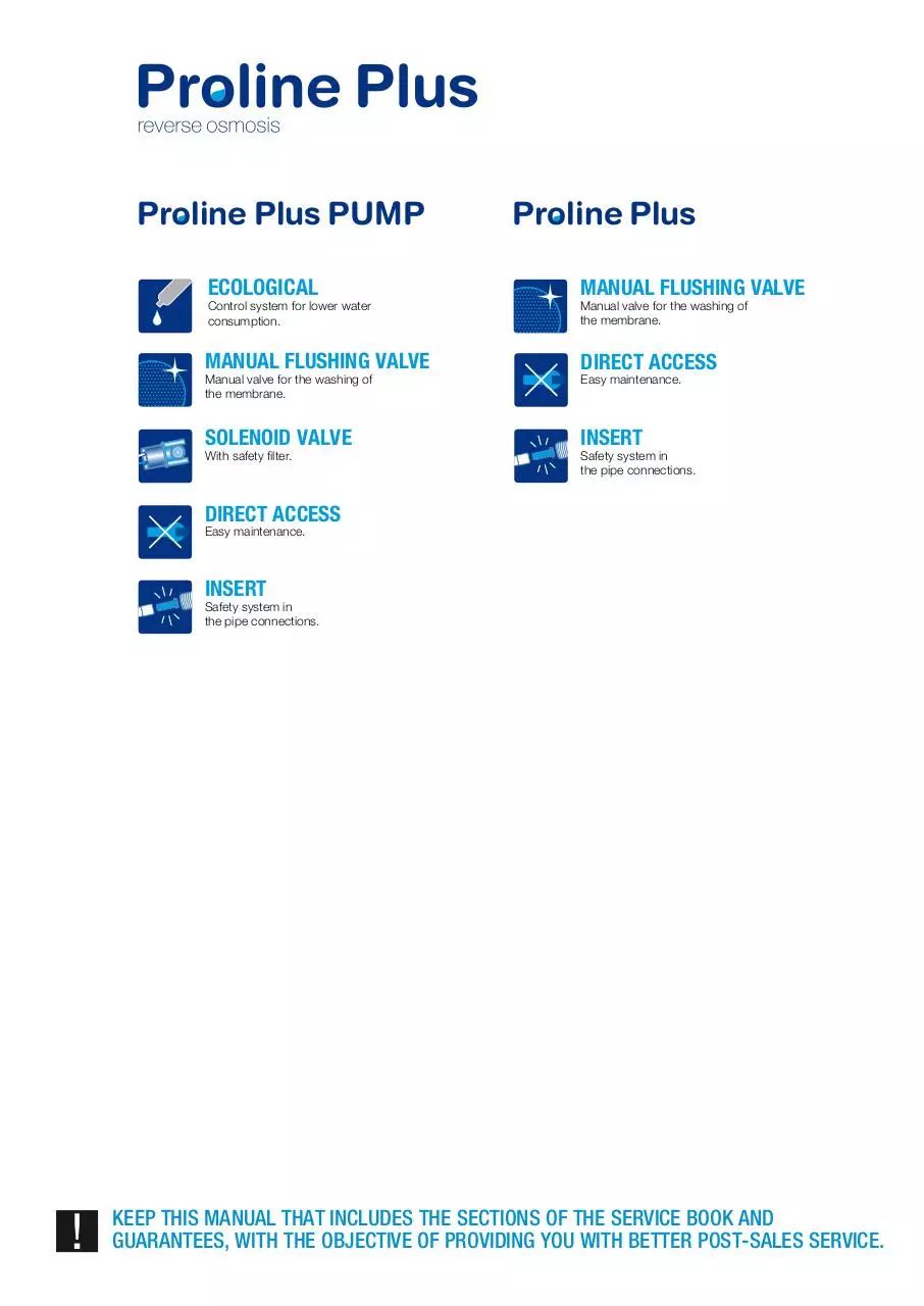
Proline Plus PUMP
Proline Plus
ECOLOGICAL
MANUAL FLUSHING VALVE
MANUAL FLUSHING VALVE
DIRECT ACCESS
SOLENOID VALVE
INSERT
Control system for lower water
consumption.
Manual valve for the washing of
the membrane.
With safety filter.
Manual valve for the washing of
the membrane.
Easy maintenance.
Safety system in
the pipe connections.
DIRECT ACCESS
Easy maintenance.
INSERT
Safety system in
the pipe connections.
KEEP THIS MANUAL THAT INCLUDES THE SECTIONS OF THE SERVICE BOOK AND
GUARANTEES, WITH THE OBJECTIVE OF PROVIDING YOU WITH BETTER POST-SALES SERVICE.
Proline Plus PUMP
g
h
NUMBER
REF.
1
205800
Filter housing 2 pieces (cap and cup)
2
263100
Steel reservoir tank
i
j
k
e
l
DESCRIPTION
with plastic covering
3
263700
1/4” ball valve for tank
4
206600
Filter housing wrench
5
767201
50 GPD membrane
6
272000
1/4” polythene tube
7
205000
1/4” ball valve 1/4” male tube
8
264900
3/8” – 3/8” + 1/4” drill
9
295201
220 – 24 V 1A transformer
10
294400
shut off (only in version without a pump)
11
746700
300 cc flow restrictor
f
c
b
k
d
a
g
i
d
h
l
with manual ball valve
12
264700
1/4” drain clamp
13
296200
Store tap
14
294100
Low pressure switch
15
294200
High pressure switch
16
291600
Granulated carbon post-filter
17
292900
Membrane container
18
294801
24 V electro valve with mesh filter
19
293500
UP7000 24 Vdc pump
20
-
21
209200
5 μm sediment filter
22
213600
Activated granulated carbon cartridge (GAC)
23
214000
Activated granulated carbon cartridge BLOCK
KEY
Metallic structure depending on model
DESCRIPTION
a
5 μm sediment filter
b
Activated granulated carbon cartridge (GAC)
c
Activated granulated carbon cartridge BLOCK
d
Pump transformer
e
Flow restrictor with ball valve
f
UP7000 24 Vdc pump
g
Activated granulated carbon (GAC) post-filter
h
Membrane container
i
High pressure switch
j
Low pressure switch
k
Tank shut off valve
l
Reservoir tank
m
Shut off valve
n
electro-valve shut up
n
j
e
Proline Plus
a
b
c
Content
Page
01. PRESENTATION
2
02. INTRODUCTION
2
02.1 What is natural osmosis and reverse osmosis?
02
02.2 How does the membrane of your system work?
3
02.3 Concentration of salts and other substances reduced by the reverse osmosis membrane
3
02.4 The effect of pressure and temperature in a reverse osmosis system
3
02.5 The effect of the concentration of salts in the feed water
4
03. TECHNICAL CHARACTERISTICS
5
04. UNPACKAGING AND VERIFICATION OF CONTENTS
5
05. WARNINGS
6
05.1 Conditions for the proper working of the system
06 6
05.2 Installation of the system
7
05.3 Operation and maintenance
7
05.4 Use of the system
7
05.5 Recommendations for the correct use of the reverse osmosis water
7
06. INSTALLATION OF THE SYSTEM
8
07. START-UP AND HYGIENISATION
12
08. OPERATION OF THE PROLINE PLUS SYSTEMS
17
08.1 Description of Operation
018
09. MAINTENANCE AND CONSUMABLES
19
09.1 Maintenance
19
09.2 Hygienisation
20
09.3 Flushing
21
10. IDENTIFICATION GUIDE AND PROBLEM RESOLUTION
22
11. MAINTENANCE MANUAL
24
12. EC STATEMENT OF AGREEMENT
Interior cover
13. GUARANTEE CERTIFICATE OF PROLINE PLUS SERIES
Interior cover
14. SHEET REGISTERING THE INSTALLATION AND PUTTING INTO
OPERATION OF THE EQUIPMENT
Interior cover
1
1. Presentation
2. Introduction
1. PRESENTATION
2. INTRODUCTION
Welcome to your reverse osmosis PROLINE PLUS system.
Thank you and congratulations. You have made a great choice in
choosing the reverse osmosis PROLINE PLUS Series system.
The PROLINE PLUS series systems are some of the best domestic appliances for the improvement of the characteristics
of water that you can find on the market.
The quality of the water in our environment is getting worse
every day. The reality of this is what has driven us to design
and manufacture this domestic reverse osmosis system in order to make water of the highest quality available to you.
Your PROLINE PLUS Series system provides you with different
benefits and advantages:
The PROLINE PLUS Series system provide you with a better
quality of life.
You will perceive an improvement in the taste of your drinking
water, and likewise in the taste of your coffees, juices or icecubes. Cooking with the purified water will heighten the taste
of the food. Your family will have healthier water.
The water provided is water that has a LOW MINERAL
CONTENT. Reverse osmosis water helps prolong the life of
your domestic appliances and is ideal for steam irons, coffee
makers and humidifiers.
• It is a physical system that does not use or add
chemical products to the water.
• Provides high quality water.
• Ensures high production.
• Has low maintenance costs.
• Confortable and easy installation.
It is important that you keep and read this manual carefully before the
installation and operation of the system.
Should you have any queries about the use, installation or maintenance
of this system, please contact the technical assistance service (T.A.S.) at
your distributor.
2.1 What is natural osmosis and reverse
osmosis?
Natural osmosis or direct osmosis is the most common in
nature, as a semi-permeable membranes make up part of the
majority of organism (for instance, plant roots, organs in our
body, cellular membranes etc.)
When two solutions with different concentrations of salts
are separated by a semi-permeable membrane, there is,
naturally, a flow of water from the solution that has a lower
concentration of salts to that of higher concentration. It is
necessary to apply sufficient pressure, of the water with a
higher concentration, against the membrane, in order to stop
this tendency and natural flow of the system. This process is
called reverse osmosis.
At present, reverse osmosis is the best method to produce pure
water via a physical system (without using chemical products).
As has been explained, its working principle is based on the
same as that of our own organism, where water is distributed
by natural osmosis.
The human body is mainly made up of water:
Woman > 55 - 65%
Man
> 65 - 75%
Child
> 80%
An adult body contains between 38 and 48 litres of water, 30%
of which is found in the cells. This water in the body, which is
almost completely recycled every 15 days, is the basis for the
transportation of nutrients, oxygen to cells, the elimination of
waste and it controls the body temperature.
We consume an average of 2.2 litres of water per day, including
the water found in foods.
2
2. Introduction
2.2 How does the membrane of your system work?
FEED WATER
FEED PRESURE
Membrane
The water that is going to be purified exerts pressure on the
semi-permeable membrane, to the extent that part of the
same is able to pass through the pores of the membrane
(reverse osmosis water), while the remainder of the water
(rejected water or that with high concentrations of salt) are
diverted to the drainpipe.
Given that the diameter of the membrane pores are less
than 0.0001 microns, only the water molecules and a certain
amount of minerals (sodium, potassium, magnesium, etc.)
are able to get through, eliminating the excess minerals that
our body does not need, as well as the bacteria, heavy metals, pesticides, chemical products, etc.
PURE WATER
REJECTION
DIAMETRE OF
RO 0.0001 μm PORE
DIAMETRE OF
5 μm FILTER
DIAMETRE OF
1 μm FILTER
SIZE OF
BACTERIA
SIZE OF
A VIRUS
2.3 Concentration of salts and other substances
reduced by the reverse osmosis membrane
The chemical composition and concentration of salts and
other substances of the water on entering the reverse osmosis
system has an affect on the purified water.
The TFC reverse osmosis membrane of your PROLINE PLUS
Series system can reduce the concentration of the elements
and compounds, among others, outlined in the following tables
Inorganic
ELEMENT / COMPOUND
ODIUM
CALCIUM
MAGNESIUM
ALUMINIUM
COPPER
NICKEL
ZINC
BARIUM
CARBONATES
CHLORINE
BICARBONATES
NITRATES
PHOSPHATES
FLUORIDE
CYANIDE
SULPHATES
BORON
ARSENIC
REDUCTION
90-95%
93-98%
93-98%
93-98%
93-98%
93-98%
93-98%
93-98%
93-98%
90-95%
90-95%
45-55%
93-98%
93-98%
90-95%
90-95%
40-45%
93-98%
Organic
ELEMENT / COMPOUND
HUMIC ACIDS
GLUCOSE
ACETONE
ISOPROPANOL
ETHYLBENZENE
ETHYPHENOL
TETRACHLORETHYLENE
UREA
1, 2, 4 TRICHLOROBENZE
1, 1, 1 TRICHLOROTHANE
REDUCTION
98%
98-99%
70%
90%
71%
84%
68-80%
70%
96%
98%
2.4 The effect of pressure and temperature in a
reverse osmosis system
The membrane usually rejects more than 95% of salts, however
the percentage may vary depending on the quality of the water,
the temperature and pressure.
3
2. Introduction
Conversion factors
2.5 The effect of the concentration of salts in the
feed water
BY PRESSURE
PRESSURE (BARS))
0.70
1.00
1.50
1.75
2.50
4.00
4.50
4.90
5.20
5.80
CONVERSION FACTOR
ON PRODUCTION
0.70
0.25
0.33
0.42
0.58
1.00
1.08
1.17
1.25
1.42
REJECTION OF SALTS
(%)
84
88
90
92
93
95
95
95
95
BY TEMPERATURE
90 - 95% > MAXIMUM QUALITY
80 - 90% > MEDIUM QUALITY
70 - 80% > LOW QUALITY
Below 70% the life of the membrane is finished. Using a conductivity metre or a TDS measurer compares the conductivity
of the feed water with that which comes out of the membrane
and obtains the percentage of rejection of salts.
4
Conductivity of R.O. water
Conductivity of feed water
MINIMUM PRESSURE OF
FEED TO MEMBRANE**
3.5 bars
3.8 bars
4.0 bars
4.3 bars
4.5 bars
4.75 bars
5.2 bars
** The test is carried out with a 50 GPD membrane at 14 ºC, without
counter-pressure, a hardness of 15 ºF and corrected salinity with NaCl.
** The pressure shown is calculated for a production of 6 l/h.
The life of the membrane is evaluated by the percentage of
salts rejected.
(-
Table of pressure in relation to the TDS
MAXIMUM TDS
OF FEED*
Up to 200 ppm
between 200 and 500 ppm
between 500 and 800 ppm
between 800 and 1200 ppm
between 1200 and 1500 ppm
between 1500 and 1800 ppm
between 1800 and 2000 ppm
CONVERSION FACTOR
TemperaturE (ºC)
ON PRODUCTION
6
0.38
8
0.45
10
0.52
12
0.59
14
0.66
16
0.70
18
0.77
20
0.85
22
0.88
25
1.00
28
1.09
30
1.16
32
1.23
34
1.30
Rejection of salts % = 1
The concentration of salts and substances in the water to be
treated influences the capacity of the production of reverse
osmosis water by the system, to such an extent that the greater the concentration of salts in the water to be treated, the
greater the pressure that is necessary against the membrane
in order to exceed the natural osmotic pressure and to guarantee a minimum flow of reverse osmosis water.
) x 100
3. Technical characteristics
3. TECHNICAL CHARACTERISTICS
4. Unpackaging and verification of contents
4. UNPACKAGING AND VERIFICATION
OF CONTENTS
CHARACTERISTICS OF PROLINE PLUS MODEL
DIMENSIONS (height x width x depth in mm): 400 x 140 x 150.
TANK (diameter x height in mm): 280 x 400.
WEIGHT (kg): 13
FEED TEMPERATURE (maximum / minimum in ºC): 40 / 2.
It is important, that prior to installing and starting the system
you check the box and condition of the system, with the
objective of guaranteeing that it has not been damaged during
transport.
TDS FEED (maximum in ppm): 2000**.
FEED PRESSURE (maximum / minimum):
2.5 / 6 bars. 250-600 kPa.
NOMINAL PRODUCTION (LPD): 150 LPD**.
MEMBRANE: Type 1 x 1812 50.
MEMBRANE PRODUCTION: 175 LPD*.
Soft water with 250 ppm. T: 25 ºC. Recovery 15%.
Pressure against membrane: 3.4 bars (without counter-pressure).
Any claims for damages during transport must be presented together with the delivery note or invoice to the
distributor, attaching the name of the carrier, within a period of 24 hours following the reception of the goods.
Remove the system and accessories from its carton packaging; taking away the protection.
PUMP: –.
MAX ACCUMULATION. (pre-charged tank at 7 PSI): 19 litres.
ELECTRIC CURRENT: –.
ELECTRIC ADAPTOR: –.
MANUFACTURER: Manufactured by Puricom Water Ind.
Corp. (Taiwan) for:
PURICOM EUROPE. Pol. Ind. L’Ametlla Park. C/Aiguafreda 8.
08480 L’Ametlla del Vallès. Barcelona. SPAIN.
T+34 936 934 310. F+34 936 934 329.
CHARACTERISTICS OF PROLINE PLUS PUMP MODEL
DIMENSIONS (height x width x depth in mm): 480 x 200 x 180.
TANK (diameter x height in mm): 280 x 400.
WEIGHT (kg): 15
FEED TEMPERATURE (maximum / minimum in ºC): 40 / 2.
TDS FEED (maximum in ppm): 2000**.
FEED PRESSURE (maximum / minimum):
1 / 2.5 bars. 100-250 kPa.
NOMINAL PRODUCTION (LPD): 150*.
MEMBRANE: Type 1 x 1812 50.
MEMBRANE PRODUCTION: 175 LPD*.
Soft water with 250 ppm. T: 25 ºC. Recovery 15%.
Pressure against membrane: 3.4 bars (without counter-pressure).
Throw the plastic bags away or keep them away from children as
they may cause them harm.
You shall find the following sets and elements:
COMPONENT
PROLINE PLUS domestic R.O. system
Reservoir tank
Faucet + Assembly accessory kit
Kit for drain connection
Wall adaptor for socket
Wire connection for power supply**
Blue manual 1/4” inlet valve
Instructions manual
White 1/4” tube
Reverse osmosis membrane 50 GPD
Filter housing wrench
Tank valve 1/4” tube
Sediments filter 5 μm
Granulated carbon cartridge and flat joints
Compact carbon cartridge and flat joints
Filter housing Cup
No.
2
13
12
8
7
6
5
4
3
21
22
23
1
AMOUNT
1
1
1
1
1
1
1
1
500 cm
1
1
1
1
1
1
3
*No. of exploded view on flap. ** ONLY PLUS PUMP MODEL.
PUMP: Booster.
MAX ACCUMULATION. (pre-charged tank at 7 PSI): 19 litres.
ELECTRIC CURRENT: 220-240 V. 50 Hz. 24 W.
ELECTRIC ADAPTOR: 100-240 V. 50/60 Hz. 24 Vdc 1A.
MANUFACTURER: Manufactured by Puricom Water Ind.
Corp. (Taiwan) for:
PURICOM EUROPE. Pol. Ind. L’Ametlla Park. C/Aiguafreda 8.
08480 L’Ametlla del Vallès. Barcelona. SPAIN.
T+34 936 934 310. F+34 936 934 329.
*Levels may vary some +/- 20%.
**For salinity up to 2000 ppm, consult the pressure table in relation to the TDS
in section 2 of the present manual.
See section 5 WARNINGS.
The packaging material can be recycled and must be thrown
away in the appropriate selective recycling bins or the specific
centre for the collection of waste material.
The machine that you have acquired has been designed and
manufactured with high quality materials and components
that can be recycled and re-used. This product can not be
thrown away into the usual urban rubbish. When you want to
throw the machine away, it must be taken to a specific local
centre for the collection of materials, indicating that it has
electric and electronic components (only in PROLINE PLUS
PUMP models).
5
4. Unpackaging and verification of contents
In order to obtain more information about how to dispose of your
electrical and electronic machine once they have fulfilled their
use, contact the local authorities, the management of urban
waste service or the establishment from which you acquired
the machine.
The proper collection and treatment of the machines that can
no longer be used, contributes to the preservation of natural
resources and also to avoiding potential public health risks.
5. Warnings
5. WARNINGS
The domestic systems of the PROLINE PLUS series, ARE NOT
water PURIFIERS.
Should the water to be treated come from a public water supply (and as
such complies with the legislation in force European Directive 98/83/EC),
the domestic systems of the PROLINE PLUS series, significantly improve
the quality of the water. agua.
Should the water to be treated not come from a public water supply,
that is, from an unknown source, a physical-chemical and bacterial
analysis of the water shall be necessary, with the objective of ensuring its
proper purification applying the proper techniques and systems appropriate
for each case, PRIOR TO THE INSTALLATION of the system.
Contact your distributor in order to obtain advice about the most appropriate
treatment for you.
5.1 Conditions for the proper working of the system
• Do not use hot water in the system (T > 40 ºC).
• The room temperature must be between 4 ºC and 45 ºC.
• The PROLINE PLUS PUMP series system incorporates
a pump. Should the system pressure be superior to 3 bars, a
plessure regulator should be attached prior to water entering the
system, set at a maximum pressure of 2.5 bars. (Ref. 577603).
• There is no pump incorporated into the PROLINE PLUS series
system. The installation of a system without pump is recommended when the system pressure is higher than 3 bars.
• For water with a salt content higher than 2000 ppm contact
your distributor.
• It is recommended that you soften the water to be treated
or that has a maximum hardness of 15 ºF with the objective of
obtaining the optimum performance of the system.
• Should the water to be treated have a level of hardness superior
to 15 ºF, the life of the membrane may be reduced and also the
performance of the system. It is recommended that you brush the
membrane for 15 seconds once a day (Read section 9.3 Flushing, which describes how it should be carried out).
• Should the water to be treated contain:
· high concentrations of iron and magnesium (higher than 1 ppm
on average in the rejection of the machinery),
· prolonged hyperchlorisations.
· sludge or turbidity superior to 3 NTUs,
· a concentration of nitrates superior to 100 ppm.
· a concentration of sulphates superior to 250 ppm,
· contact your distributor so that they can recommend the most
appropriate pre-treatment for you, and as such ensure the
proper working of the machine, avoid damage to components
and guarantee the quality of the water supplied.
6
5. Warnings
5.2 Installation of the system
• Should it be necessary to condition the installation of the
home in order to install the system in the foreseen location, it
must be carried out in accordance with the national legistation
in face.
• The PROLINE PLUS PUMP series system needs an electrical
socket that is at least 1 metre away.
• The location foreseen for its installation must have sufficient
space for the machine itself, its accessories, connections, and
to carry out maintenance comfortably.
• Under no circumstances must the system be installed outdoor.
• The systems should not be installed next to a heat source or
where it receives a direct flow of hot air (dryer, refrigerator, etc.)
• The surroundings and setting where the system and tap
are to be installed must meet appropriate hygiene-sanitary
conditions.
• Avoid external drips from pipes, drains etc. onto the machinery.
5.3 Start-up and maintenance
• The PROLINE PLUS series systems, needs to undergo
periodic maintenance carried out by qualified technical
personnel, with the objective of guaranteeing the quality of the
water produced and supplied.
• The consumable elements must be substituted with
the frequency indicated by the manufacturer (See section
9. Maintenance).
• The system must be hygienised periodically and prior to its
start up.
• Following the start up, the first two deposits must be thrown
away.
• The system must be maintained by qualified technical
personnel, carried out under the proper hygienic conditions, with the objective of reducing the risk of internal
contamination of the machine and its hydraulic system.
(For more information contact the technical service of your
distributor).
• Following a prolonged period (more than a month) during
which the system has not been in operation or produced water, contact your distributer in order to carry out the proper
hygienisation and maintenance.
• In order to improve the performance of the system, extract
full jugs and bottles and avoid the occasional extraction of
glasses.
• Special attention must be paid to the regular cleaning and
hygiene of the faucet of the reverse osmosis system, and
especially during the periodic maintenance. Use the Oxibac
spray (Ref. 65220) for this and disposable kitchen paper or a
multiuse cloth for cleaning the kitchen.
5.5 Recommendations for the correct use of the
reverse osmosis water
• If you want to feed any other consumption point with
osmosis water (such as a fridge with an ice-cube dispenser,
another faucet, etc.), the piping should not be done with
a metal tube, as this will give the water a bad taste. Use a
similar plastic tube (Ref. 272000).
• The water supplied by the domestic reverse osmosis systems
has a LOW SALT CONTENT. The mineral salts required by the
human body are provided by food, especially by dairy products
and to a lesser degree by the water we drink.
5.4 Use of the system
• When you are going to be away from home for more than a
week close the water inlet, empty it and disconnect the electric current. On your return connect the electric current of the
same, open the inlet and empty the reservoir tank twice before
consuming the water.
7
6. Installation of the system
6. INSTALLATION OF THE SYSTEM
1
2
3
4
5
6
7
8
9
10
11
12
13
14
15
16
17
18
19
20
Given that the appliance that you are going to install
improves the quality of the water that you are going to
consume and is considered a food, all of the tools that
you are going to use for the assembly and installation
must be clean and under no circumstances contaminated
or impregnated with grease, oils or rust. The work must
be carried out under adequate hygienic conditions, taking
the necessary precautions with everything related to the
materials that are going to be in contact with the water to
be treated or consumed. (For more information contact
the distributor).
The most usual place for the installation of the system is under
the sink in the kitchen or in a cupboard next to it.
GLYCERINE
GLICERINA
The installation of your PROLINE PLUS reverse osmosis
system must be carried out by qualified personnel from an
authorised technical service. Follow the recommendations in
Section 5 of this manual.
TOOLS FOR INSTALLATION,
MAINTENANCE AND START-UP:
TOOL
REFERENCE
IMAGE
Adjustable wrench
-
1
Vice grip pliers
-
2
Drill
-
3
12 and 6 mm drill bits
-
4
Edible glycerine
-
5
No. 2 Allen wrench
-
6
No. 14/15 mm double socket wrench
-
7
Flat-head screw driver
-
8
Electric multi-metre
-
9
Teflon tape
-
10
Pressure gauge
Ref. 270700
11
Membrane housing wrench
Ref. 206601
12
Filter housing + 2 x 1/4” connections
Refs. 205200 + 277100
13
Portable pressure measurer
Ref. 268100
14
Portable conductivity measurer
Ref. 267900
15
Chlorine analyser
Ref. 271700
16
Filter housing wrench
Ref. 206600
17
Oxibac spray
Ref. 652200
18
Hygienisation kit
Ref. 743303
19
CONTENTS: test holder, gloves, 2.5 ml syringe, paper towels,
Jar for mixing and OSMOBAC disinfectant
Cutter
Contact your distributor
8
20
6. Installation of the system
6. Installation of the system
1. Once it has been decided whether to put the tap on the
counter top or sink (usually in the corner), a hole is drilled in
the same with the 12 mm bit, to pass the connecting pipe
through Image 21.
Use the metal escutcheon to choose the location of the drill.
If the metal escutcheon of the tap creates any difficulty in its
assembly due to the geometrics of the counter-top or fridge,
use the rubber joint supplied instead of the metal escutcheon
in order to assemble the tap.
21
22
23
24
365
280
480
450
190
4. Using the white 1/4” tube, exploded view No. 6 on flap, connect the tap with the connector marked “faucet-grifo”. Prior to
this cut the tube to the required length.
In order to carry out all of the connections, foresee a longer tube,
so as to facilitate the movement of the system once installed,
without out having to disconnect unnecessarily or make access to the
same more difficult.
Choose the bit and the type of drill that is appropriate for the material
in question.
2. Prior to this, insert the metal escutcheon and a thick flat
rubber joint into the connecting pipe (these must be on
the upper part of the counter-top). Then pass the threaded
connecting pipe through the hole. Once this is done, on the
bottom end of the connecting pipe you connect: the rigid
plastic washer, the grower washer and the hexagonal nut.
They should be tightened together with the No. 14/15 mm
square wrench, until the tap is completely static and properly
positioned.
The tap will be positioned as required after the final tightening
(it is recommended that the tap handle is orientated towards
the exterior of the counter top). Image 22. If the counter-top is
thicker than that of the connecting pipe of the tap, you can use
the tap extension (Ref. 261900). Finally, cut the left over part
of the wide flat joint with a cutter in relation to the escutcheon.
Image 23.
3. Choose the location of the system and also foresee the
space required for the reservoir tank. Image 24.
Fix the system to the wall using the brackets of the lower part
of the same and the proper screws.
It is recommended that the cups are situated on the floor,
with the objective of not straining the cupboard wall once the
system is filled with water.
Carry out the connection of the tap via inserting the metallic
nut, biconic and through the end of the 1/4” tube. Images 25
and 26. Introduce the end of the tube into the interior of the tap
connector and screw the nut using the T-bar or until you are
sure it has been connected properly.
Carry out the connection to the system in the connector
marked “faucet-grifo”
Unscrew the nut from the connector, remove the protector,
introduce the screw into the end of the 1/4” tube coming out
of the tap and screw it into the connector of the system. Image
27.
exploded view No. 6 on flap
25
26
27
FAUCET
robinet
Hahn
GRIFO
9
6. Installation of the system
5. Following this you should make the hydraulic connection of
the appliance to the system. As the system is under pressure
the stopcock situated in the cold water outlet must be closed.
Image 28.
Depending on how old the installation is, there may be no right
angle valve and that it is necessary to turn off the general stopcock in the home.
Immediately afterwards, depressurise the installation by turning
on the tap of the sink and wait until water comes out of it.
Make sure that the connection to the appliance is going to be carried
out in the cold water pipe connection. If the connection is made in
the hot water pipe it may damage important components of the system.
(Generally the cold water pipe connection is found to the right).
Unscrew the connection of the hose or the flexible pipe,
image 29. Have a recipient or cloth ready to collect or wipe
up the water that may come out of the flexible pipe when
you unscrew it. Insert it into the connection in the wall and
the valve or flexible pipe to the 3/8” wall adaptor, exploded
view No. 8 on flap.
The flat 3/8” joint that is inserted makes it unnecessary to
use a sealant. (Teflon wire, liquid Teflon, hemp twine, etc.),
image 30.
Assemble the 1/4” manual in-let valve in overlap in the left hole
of the wall adapter. Image 31.
29
28
CLOSED
29
on brass threads. The two connectors (3/8” and 1/4”) must
be screwed in with a monkey wrench until you are sure that
it is properly assembled and water-tight. Subsequently, in the
male connector of the 3/8” adapter connect the flexible pipe
(usually female).
Should it be necessary to install a special component, it should not
be iron or contain iron components as on rusting these can
reduce the performance of the appliance.
To ensure the proper installation and water-tightness of the
connections made, open the right angle entry valve (or where
applicable the general stopcock), first making sure that the tap
of the reverse osmosis appliance on the counter-top has been
turned off. Once the stopcock is open, turn on the tap on the
counter-top to bleed the air that may be inside (beware of any
spurts or splashes of water).
Check the 1/4” valve, as depending on how old it is and the
material used in the assembly of the interior installation of
the house, in some cases, it becomes blocked due to the
incrustations there are in the installation and which come
loose once there is water coming through and pressure.
Next, the white 1/4” tube is connected, between the stopcock and the connection of the appliance marked “feed water/entrada”, image 32. Make sure of the correct entry into
the tube and tightening of the corresponding nuts. The 1/4”
feed valve must remain closed until the end of the installation
of the machine.
32
feed water
31
exploded view No.8 on flap
30
A sealant should be added to this valve to ensure that it has
been assembled correctly and that it is water-tight. The use of
Teflon is recommended, as it is a clean, quick sealant and safe
10
6. Subsequently, the drain clamp must be assembled,
exploded view No. 12 on flap. Bear in mind that this clamp is
designed to be assembled on a 40 mm diameter drainpipe
tube. Should this not be the diameter of the drainpipe tube,
contact your components supplier to make the correct
connection.
Using the drill, and this time a 6 mm bit, make a hole between the mouth of the drainpipe of the sink and the u-bend
(it is recommended that you do it in the upper part of the
tub, so that any rubbish thrown away from the sink does
6. Installation of the system
not obstruct the hole or water flow outlet). Envisage the
space necessary for the assembly of the clamp, image 33.
Next the drainpipe collar shall be assembled, but making sure
that the hole that you have made is completely aligned over
the front part of the 1/4” connector (part where the square
pad goes), done by putting the bit, used for making the 6 mm
hole there, through the hole there is between the clamp and
the drainpipe; thereby avoiding any obstacle to the passing of
water towards the same.
exploded view No. 12 on flap
You should connect the other end of the 1/4” tube to the connector of the machine marked “tank/depósito”. Image 38.
exploded view No. 3 on flap
36
33
37
Put the nuts in the socket on the bottom part of the clamp and
afterwards put in the corresponding screws. The nuts must be
screwed in carefully and progressively, alternating between the
two. Try not to force the components. Image 34.
The 1/4” tube must be connected, between the thread of the
drainpipe clamp and the connection of the machined marked
“drain-desagüe”, image 35.
Use the wrench to ensure that the tube in the nut of the drainpipe clamp is tightened properly (for the proper positioning of
the tube in relation to the nut, this should stick out of the front
part of the same some 2 mm).
34
35
DRAIN
Abwasser
DESAGÜE
7. Make the connection of the reservoir tank and the connector of the machine marked “tank/depósito” using the 1/4”
tube. To do this, put Teflon on the connector of the tank and
screw on, over this, the right-angle valve exploded view No.12
on flap and image 36. Connect the 1/4” tube to said right-angled valve. Image 37.
38
TANK
reservoir
Produktwasser
DEPÓSITO
8. If necessary a socket shall be put in near to the machine
(< 1 m) for the electrical feed of the same, according to the
National legislation in force (only in the PROLINE PUMP PLUS)
image 39.
9. Make sure that all of the connections have been screwed
in properly.
Remember that when the pressure is superior to 3 kg/cm2, a
pressure regulator should be inserted into the feed tube to the
machine (Ref.577603), set at a pressure of 2.5 kg/cm2.
39
40
10. Should you wish to feed any other consumer point (tap,
fridge with ice-cube dispenser, etc.) use a 1/4” plastic conductor Ref. 272000) and a 1/4” te (Ref. 279300) for every
extra pipe connection you need.
11
6. Installation of the system
11. Check that the pressure of the reservoir tank is 0.5 bars
(7 P.S.I.), using the portable pressure gauge and the valve that
is at the bottom of the tank. If this is not the case, fill or empty
the pressurised tank until you achieve the indicated pressure.
Image 40.
7. Start-up and hygienisation
7. START-UP AND HYGIENISATION
Following the installation of the system, you shall proceed to
put it into operation. It is recommended that this be carried out
by professional technical personnel and in accordance with
the following procedure.
Respect the order of the filter cartridges in order to guarantee the
proper working of the system.
7.1 Hygienisation
1. Cut the top of the hygienisation kit and place the contents onto
a clean surface, with the objective of reducing contamination.
Images 41 and 42.
41
42
2. Empty the contents of the bag for the Osmobac hygienisation
into the 150 ml recipient, fill the recipient with tap water and shake
until it is completely dissolved (for approximately 2 minutes).
Images 43 and 44.
3. Open the wrapping of the membrane and put it into the
plastic bag of the kit to hygienise it. Images 45 and 46.
Following this, use the syringe to collect 2 ml of the Osmobac
solution you prepared before, empty it into the plastic bag with
the membrane inside and fill it with potable water from the tap
until the membrane is completely covered. Leave it there for
between 15-30 minutes. Images 47, 48 and 49.
12
7. Start-up and hygienisation
45
46
Place the corresponding filtering cartridge into each housing
following the order outlined below: the sediments cartridge
should be put into the housing that incorporates the feed water connector to the machine “feed water/entrada” (right), put
the cartridge with granulated carbon (GAC) in the centre and
put the cartridge with the carbon bloc on the left.
While assembling the carbon cartridges make sure that the flat
joints of the edges are concentric with the carrier edge and
their corresponding heads and re not being pinched.
Check that the o-ring joints of the housing are not defective.
Cover the o-ring joints slightly with edible glycerine to ensure
that they slide and do not become pinched when the housing
is being tightened. Image 51.
50
51
NA
44
G
LI
CE
RI
43
47
48
6. Keep the 1/4” in-let valve closed, open the right-angled key
and connect the system to the mains. (PROLINE PUMP PLUS
version). Image 52.
49
exploded view No. 4 on flap
7. Disconnect the in-let tube to the membrane carriers and
orient it to an external recipient. Images 53 and 54.
8. Open the 1/4” in-let valve, image 55 and wash out the filter
52
CLOSED
53
4. Keep the 1/4” in-let valve closed.
5. Take the cartridge filters out of their packging and take
away the protective film with which they are covered in order
to guarantee the hygienic conditions that the transporting
and manipulation of the same requires.
Keep the plastic bags away from children as they are a danger
to them.
Dismantle the filter housing cups using the wrench exploded
view No. 4 on flap and image 50.
system until the water comes out clear. In this way the powder
generated by the granulated carbon in the filters during the transportation and manipulation of the same is eliminated. This dust
must be eliminated as it could completely or partially block the
reverse osmosis membrane.
13
7. Start-up and hygienisation
54
55
OPENED
9. Close the 1/4” y water in-let, and reconnect the tube to the
membrane carrier entrance.
10. Keep the valve of the reservoir tank closed, image 56.
11. Insert the filter-housing, between the water in-let and
the feed connection of the system in order to carry out
the hygienisation. Image 57. Keep the filter-housing on a
recipient or in the interior of the sink.
56
CLOSED
57
14. Open the in-let valve and let the product that is in the
filter-housing flow through the system until water comes out of
the tap of the system on the counter and through the drain,
afterwards, close the tap on the counter top. (If the post-filter
is new, dark water will come out of the tap for the same reason
as explained in point 3 of this section). Carry out this action
every 30” and repeat as of point 12. Remember that every
time you want to open the water-housing you must close the
in-let valve, turn on the tap, wait until the system depressurises (10”) and throw away part of the water contained in the
inside of the filter-carrier so that you can refill with the amount
of Omobac solution indicated before in point 12.
Carry out 5 washes in the manner outlined before going onto
the next point.
15. When the filter-housing fills up for the last time, pour in
20ml of the Omobac solution. Keep the valve of the reservoir
tank closed.
16. Open the tap of the reverse osmosis appliance, the in-let
valve and let the product that is in the filter-housing flow through
the system until water comes out of the tap of the system on
the counter and through the drain, afterwards, close the tap on
the counter top.
17. Immediately afterwards, open the valve of the reservoir
tank for 10”, Image 61 and close it once again after this time.
60
61
OPENED
12. Open the filter-housing and pour 15 ml of the Osmobac solution inside (dose that can be given with the syringe).
Images 58 and 59.
58
59
18. Following this and after 1 minute, close the 1/4” in-let valve
and let the product settle in the system for between 15 and
30 minutes.
19. Once this time has passed, open the counter-top tap of the
system, empty the tank and wait until water stops coming out.
13. Close the filter-housing and open the tap of the reverse
osmosis appliance on the counter top Image 60.
14
20. Keep the tap of the appliance open. Following this, open
the manual flushing valve and open the 1/4” in-let valve allowing the potable water from the system move the product and
residues of the hygienisation through the drain for 2 minutes.
7. Start-up and hygienisation
After this time close the manual flushing valve. Keep the
counter-top tap on for 3 minutes allowing the products
and remains of the hygienisation to be eliminated through
the tap of the appliance. Subsequently, open the valve of
the reservoir tank, turn off the tap on the counter-top and
wait 2 minutes until the reservoir tank is full.
Immediately afterwards, you should close the 1/4” in-let valve
and turn on the tap on the counter-top to completely empty
the tank, wait until water stops coming out.
Check the level of chlorine coming out of the tap of the
appliance, using the chlorine measurer.
Before opening the membrane-housing make sure you have
a recipient ready where you can partially empty it into, as it will
be full of water. Check the internal pressure of the reservoir
tank which should be 7 psi approx. (0.5 bars).
24. Use the damp cloth that was in the hygienisation kit, clean
the system. Use kitchen towel paper to dry all of the parts that
may have got wet. Image 67.
65
66
67
G
64
CE
LI
CHLORINE TEST
NAE
RI
Repeat this rinsing process and control until the level of chlorine
is below mg/l (1 μm).
21. Dismantle the filter-carriers used for the dosing of the
Osmobac and connect the feed tube into the connection
“feed, entrada” of the appliance.
22. Put on the gloves supplied in the kit, rinse the membrane
with potable water for a while. Image 62.
62
63
23. Once you have carried out the rinsing, the in-let valve
must be kept close. Following the strictest hygienic measure,
assemble and position the membrane correctly in its container,
taking the precaution to lubricate its joints with edible glycerine.
Images 63, 64, 65 and 66.
Pay special attention to the hygienisation of the tap pipe. Use
the Oxibac spray and disposable kitchen paper, image 68,
or soak the kitchen paper with remainder of the Osmobac
solution. Image 69.
Rub the pipe and the outside of the tap with the disposable
paper and do not touch it directly with your hands. Image 70.
Under no circumstances should you use the kitchen towel you
use to dry your hands or the multi-use cloth used for cleaning
in the kitchen.
25. Turn off the counter-top tap, open the in-let valve and keep
the electric current of the system on (PROLINE PUMP PLUS
version), give the system a once over to ensure that there are
no leaks (for 1 minute approx).
To ensure the proper working of all of the components of the
system, close the valve of the reservoir tank, thus pressurising
the system quickly. Image 71.
Should the pump of the system not stop (PROLINE PUMP
PLUS version), check the maximum rate of the pressure
15
7. Start-up and hygienisation
switch with a No. 2 Allen key, until you are able to stop the
pump. Image 72.
Once you have carried out the check, open the valve of
the pressurised tank again. Image 73.
TDS TEST
TDS
68
70
69
71
CLOSED
29. Sometimes the water that is produced is cloudy, caused
by micro air-bubbles (due to the air pockets there may be in
the interior of the system). Under no circumstances does it
prejudice the quality of the drinking water. This aspect of the
water will slowly disappear as the air is eliminated from the
interior of the system.
30. All of the materials used to carry out the hygienisation must
be thrown away into the appropriate recycling container.
26. The system is now properly hygienisised.
27. Turn on the counter-top tap and using the conductivity
measurer or the TDS check the quality of the water coming
out after it has been running for a few minutes. Check that the
reduction of salt is appropriate.
72
73
OPENED
28. Given that the hygienisation and rinsing does not ensure
the complete elimination of the residues (carbon powder
from the filters, washing of the tank, residues of the hygienisation, etc.), the reservoir tank must be emptied twice
before consuming the water produced.
16
8. Operation of the PROLINE PLUS systems
8. OPERATION OF THE PROLINE PLUS SYSTEMS
VALID LIST FOR PROLINE PLUS PUMP AND PROLINE PLUS
1
Connection kit and manual valve
10
Manual valve of reservoir tank
2
Turbidity filter
11
Pressurised reservoir tank
3
Granulated Active Carbon filter (GAC)
12
Activated carbon post-filter
4
Pressed Activated Carbon filter (BLOCK)
13
Counter-top tap
5
Shut off valve
14
Low pressure switch
6
Reverse Osmosis membrane
15
Shut off electro-valve
7
Restrictor with manual wash valve
16
Booster pump
8
Connection to the drain
17
High pressure switch
9
Check valve
PROLINE PLUS PUMP
Electrical diagram of proline plus pump
Low pressure
switch
High pressure
switch
MOTOR
PUMP
24 Vdc
In-let solenoid
valve
17
8. Operation of the PROLINE PLUS systems
PROLINE PLUS
8.1 Description of the operation
The water in the system to be treated, goes through the
manual in-let valve (1) and enter in the appliance going
through the turbidity filter (2), carbon filter (GAC) (3) and
carbon filter BLOCK (4).
In this phase of filtration, the particles in suspension, the
chlorine, its derivatives and other organic substances are
retained.
The passing of the water towards the interior of the system is
controlled via the shut off valve (5) or via the electro shut-off
valve (15) in the PROLINE PLUS PUMP models.
The water, after leaving the filtration phase, is pushed towards
the reverse osmosis membrane (6) via the pump (16) (only in
the PROLINE PLUS PUMP).
The PROLINE PLUS PUMP models incorporates a minimum
pressure switch (14) that protects the pump, against falls in
pressure in the system, stopping the operation and closing the
electro in-let valve (15) when this situation is detected. The water pressure against the membrane makes the reverse osmosis
process possible. On the one hand, the reverse osmosis water,
after going through a check valve (9) is stored in a reservoir tank
18
(11) and, on the other hand, the water with excess salts and
unwanted substances go to the drain (8) for their elimination
through the flow limiter (7).
When the reservoir tank is full the water to the system is cut off
using the shut off valve (5). In the case of the PROLINE PUMP
PLUS model, the high pressure switch (17) detects that the
tank has filled up, stopping the pump (16) and closing the
electro in-let valve (14).
On getting water from the appliance tap (13), the water accumulated in the tank (11) passes through a carbon post-filter
(12) the objective of which is the elimination of possible colours
and tastes that the water can retain before being dispensed.
The PROLINE PLUS series systems have a manual brush
valve or a membrane wash (7). Turn this valve the amount of
times indicated, following the steps described in section 9.3
(Flushing) of this manual.
9. Maintenance and consumables
9. Maintenance and consumables
GAC carbon
pre-filter
REF. 213600
With the objective of guaranteeing the quality of the water supplied
by your system, it should have regular maintenance checks carried
out by qualified technicians.
MAINTENANCE RECOMMENDATIONS
BY YOUR OFFICIAL PROLINE PLUS
SERIES DISTRIBUTOR
Pre-filter sediments:
Maximum 12 months
GAC and BLOCK carbon filters: Maximum 12 months
Reserve osmosis membrane:
Every 3 years approx.
in so soft water < 15 ºF
Post-filters:
From 12 to 24 months
Hygienisation:
Every 6-12 months.
Each time components in contact with water
from the system are accessed or water has not
been consumed for more than a month.
NOTE: The membrane must be substituted if a specific compound is higher than the
maximum advisable permitted limit for drinking water, European directive (98/83/EC).
An excess of a compound (total chlorine, turbidity, hardness
etc.) can lead to a reduction in the life of the filters and certain
components.
The maintenance tips are guidelines. Your official distributors
of the PROLINE PLUS series will determine the duration of
the consumables in relation to the quality of the water and the
foreseen consumption.
50 GPD membrane
REF. 767201
n
bo
ar
50
The period they last depends on the quality of the local water,
on specific aspects such as the external turbidity, high chlorine
levels, excess iron, etc.
5 μm sediments filter
REF. 209200
C
GP
D
WARNING: Some of the components of your system, such
as the sediments pre-filter, the granulated carbon filters,
the reverse osmosis membrane and the granulated carbon
post-filters, are consumable and last for a limited time.
Carbon block
post-filter.
Ref. 214000
HYGIENISATION KIT
It is important for the maintenance of your system to be carried
out by the official service of the PROLINE PLUS series, which will
use original spare parts and offer you information, a maintenance
contract and service guarantee.
Any manipulation of the system or use of a spare part that is not
original by a company or person that does is not a member of our
distributors shall invalidate the guarantee of your system as well
as that of your official distributor.
ORIGINAL PROLINE PLUS
CONSUMABLES
Hygienisation kit
REF. 743303
Activated carbon post-filter
REF. 291600
See the hygienic conditions to take into consideration during the manipulation of the
system described in the sections above.
9.1 Maintenance
1. Close the manual in-let valve, empty the tank of the system
by opening the tap and disconnect it form the electric current.
(PROLINE PLUS PUMP version).
2. Following this, replace the post-filter (if applicable or if you
have not done so before).
Disconnect the tube, image 74, and unscrew the connectors
at both sides of the post-filter, images 75 and 76. Try to avoid
74
75
Take hygienic precautions during the manipulation of the consumables
and after removing them from their packaging
19
9. Maintenance and consumables
forcing the other components. In the case of the PROLINE
PLUS PUMP model, fix the in-let nipple with the vice grip
pliers, to avoid it unscrewing in relation to the pressure switch,
and on a par with the post-filter with the other hand.
Unwrap and take out the protective caps and assemble the
new post-filter, images 77, 78 and 79.
Make sure you assemble in the correct position. Screw the
outlet elbow, previously disassemble, respecting the original
76
6. Extract the membrane from inside the membrane housing,
images 82 and 83 and apply the hygienisation procedure described in section 7 (Start-up and hygienisation).
82
83
77
Carbon
Carbon
Use the membrane housing wrench to disassemble the top
and the vice grip pliers to extract the interior membrane.
Images 84 and 85.
78
79
position (entrance and exit), image 80. Both connectors should
have been covered with teflon beforehand (use teflon tape). In
the model with a pump, screw the post-filter to the male of the
exit of the maximum switch, avoid the male turning in relation
to the switch, image 81 having covered it with Teflon.
80
81
84
85
7. Replace the filtering cartridges, disassembling the filterhousing cups following the procedure outlined in section 7
(Start-up and hygienisation). Repeat the steps for the cleaning
of the filters described in section 7.
9.2 Hygienisation
It is recommended that you carry out a hygienisation of the
system similar to that described in Section 7, (Start-up and
hygienisation), each time the six-monthly or yearly maintenance check is carried out (depending on use, water quality
or evaluation of your distributor), as well as each time that the
components in contact with water in the system are manipulated and following a large period without producing water
(more than one month).
Finish screwing the post-filter and its outlet elbow so that this
is properly positioned, with the objective of avoiding forcing the
1/4” exit tube. Connect this tube using its 1/4” nut of the exit
of the post-filter.
20
9. Maintenance and consumables
9.3 Flushing
Flush the membrane once a day to clean it of any deposits or
incrustations it may have on its surface. This flushing will remove
these elements and they will be eliminated down the drain.
For this, after the continuous extraction of more than 2 litres of
water, image 86, open the 15” cleaning valve manually and close
it immediately afterwards. Images 87, 88 and 89. By this simple
action, you are able to prolong the life of your membrane.
86
88
87
opened
89
CLOSED
21
10. Identification guide and problem resolution
10. IDENTIFICATION GUIDE AND PROBLEM RESOLUTION
SYMPTOM
CAUSE
SOLUTION
1. Leak from tap.
Turn off components worn.
Joint pinched or worn.
Substitution of tap.
Change joints.
2. Exterior leak to the
system in sink
cupboard.
By base of tap.
In drain.
In feed.
In feed tubes of the system.
Check condition of tap and if necessary substitute it.
Tighten or replace.
Check to see if there is sufficient teflon in the in-let valve or substitute it.
They are tightened too close to the wall. Do not have holding pins. They are
in bad condition. (substitute them) or not pushed into connectors enough.
3. No production.
There is no water supply.
Electro in-let valve closed.
Pre-filter blocked.
Membrane is saturated.
Wait until supply returns.
Check condition of coil and clean it. Change it, if necessary.
Change filter.
Change membrane. Check condition of restrictor.
If blocked, clean or substitute.
Clean or substitute.
Check supply in the house. Check the tension at the exit of the transformer.
(if there isn’t any, change it).
Valve cleaned /restrictors.
There is no electricity supply.
4. Little production.
Low pressure in the membrane feed.
Excessive rejection.
Check system pressure, and where necessary put in pump and minimum
pressure switch.
Open it.
Open it.
Check tank pressure and if necessary pressurise up to 7 PSI.
Check if water is coming out of the air valve.
Substitution of the same.
Look at flow of the post-filter outlet and if this is the case, substitute it.
If pinched, substitute the membrane.
Check production flow.
If there is very little, and pressure is good, substitute it.
Check that the pump generates between 6 and 7 Kg. /cm2 at the entrance
of the membrane carrier. If this is not the case, substitute the head.
Check the flow of the restrictor, and if necessary substitute it.
5. Excessive production.
Membrane housing in bad condition.
Membrane housing empty.
Nut joints in bad condition.
Connection of piping not carried out properly.
Rejection and production may be connected. Substitute it.
Put in membrane.
Production and rejection connected. Substitute joints or membrane
Check system flow.
6. High T.D.S.
Membrane housing in bad condition.
Production and rejection connected. Substitute membrane and/or joints.
7. Metallic, bitter or
acidic taste.
Water has low pH.
Put in re-mineralising post-filter before closing.
8. Plastic or synthetic
taste.
Post-filter saturated.
Change post-filter.
9. Unpleaseant taste
or smell.
Contamination.
Change filters, membrane and hygienisation.
10. Colour of water is
whitish.
Air in the system.
Wait. There is no problem.
In-let valve partially closed.
Tank valve closed.
Air tank empty.
Water tank has a hole/s.
Pre-filter very dirty.
Membrane with tip of joint pinched.
Membrane very obstructed.
Pump in very bad condition.
22
10. Identification guide and problem resolution
SYMPTOM
11. The rejection never stops.
CAUSE
SOLUTION
Electro in-let valve dirty or deteriorated.
Check if rejection stops with the reverse osmosis
system unplugged. Should it not, clean or substitute.
Put in a pressure regulator.
Check that there is 0.5 Kg/cm2 or 7 PSI air pressure
Excess feed pressure.
Tank has little air.
Deteriorated check valve.
Maximum pressure switch badly regulated or broken.
Wash valve open.
with an empty tank.
Substitute.
Check regulation and where applicable substitute.
Clean if dirty.
If in bad condition substitute it.
12. Appliance starts sporadically,
without consuming water.
Stop valve in bad condition.
Leak somewhere in the product or tap.
Excessive feed pressure.
Substitute.
Repair product or substitute the tap.
Put in feed pressure gauge.
13. Osmosis does not start.
There is no water supply.
Check the general stopcock and
the system feed.
Check general electricity supply.
Check the tension at the exit of the
Transformer and change if necessary.
Check the electric wiring.
Check the condition of and proper
Connection of the switches.
Electro-valve punctured or coil burnt. Replace it.
There is no electric current.
Electro-valve not in good condition.
14. Appliance constantly
stops and starts.
15. The pump works but
generates no pressure.
Very low feed pressure.
(lower than 0.75 bar).
Minimum switch in bad condition.
Electro-valve coil in bad condition.
Jump low pressure switch.
Short circuit in a component or in the wiring.
Find it, repair and/or substitute it.
Diaphragm in bad condition.
Substitute the diaphragm or change completely.
Transformer in bad condition.
Check and substitute.
Substitute it.
Substitute it.
23
11. Maintenance manual
DATE
24
TYPE OF SERVICE
/
/
COMPLETE MAINTENANCE
/
/
REPAIR
/
/
HYGIENISATION
/
/
OTHERS
/
/
COMPLETE MAINTENANCE
/
/
REPAIR
/
/
HYGIENISATION
/
/
OTHERS
/
/
COMPLETE MAINTENANCE
/
/
REPAIR
/
/
HYGIENISATION
/
/
OTHERS
/
/
COMPLETE MAINTENANCE
/
/
REPAIR
/
/
HYGIENISATION
/
/
OTHERS
/
/
COMPLETE MAINTENANCE
/
/
REPAIR
/
/
HYGIENISATION
/
/
OTHERS
/
/
COMPLETE MAINTENANCE
/
/
REPAIR
/
/
HYGIENISATION
/
/
OTHERS
NAME, SIGNATURE AND STAMP
OF AUTHORISED TECHNICIAN
SHEET TO BE COMPLETED BY THE TECHNICIAN INSTALLER.SHEET FOR THE OWNER OF THE EQUIPMENT.
EC STATEMENT OF AGREEMENT
We declare, hereby assuming all responsibility, that: the Name and position of the authorised person: José Antonio
reverse osmosis system for the filtration of water for Fogued Franco / MANAGER.
human consumption, brand: CE2, CE2 PUMP with series Date: 17/03/2006. Signed and sealed.
No.: according to manufacture, is adapted to norms or
regulations: EN-12100-1, EN12100-2,
EN-55014-1:2000/A1:2001, EN-61000-3,
2:2000/A1:2001, EN-61000-3-3:1995/A1:2001,
EN-61558-2-6 and fulfils the essential requirements of the
directives: 98/37/CE, 73/23/CEE, 89/336/CEE.
PURICOM EUROPE · C. Aiguafreda 8 · Pol. Ind. l’Ametlla Park · 08480 Barcelona · SPAIN
GUARANTEE CERTIFICATE OF PROLINE PLUS SERIES
SYSTEM GUARANTEE
PURICOM EUROPE guarantees their systems for two (2) years against any manufacturing defect, in accordance with that laid down in Law 23/2003, 10 July, Guarantees in
Consumer Goods Sales. The guarantee comprises the repair and substitution of
defective parts by authorised personnel by the Distributor or the official Technical
Assistance Service (T.A.S.), in the place of installation or in their workshops. Including
the labour and shipping costs should they arise. It does not include the substitution of
parts that have suffered usual wear and tear, lack of maintenance, hits etc. due to the
improper use of the system outside specifications provided or in those cases where it
has been modified or prepared by personnel that do not belong to the company or
official. The substituted parts under guarantee remain the property of PURICOM
EUROPE. The term of the guarantee starts on the date of purchase of the system in your
PURICOM EUROPE Distributor. For whatsoever claim under the guarantee you are
required to provide receipt of purchase. Should you suffer any problem with the system
while it is under guarantee, contact your Distributor for the substitution of the defective
part and in order to guarantee the proper working of the system. PURICOM EUROPE
has the exclusive responsibility to replace or repair the defective parts. Compensation or
other expenses are not covered.
GUARANTEE OF INSTALLATION AND PUTTING INTO OPERATION
The distributor guarantees that the system installed is appropriate for the improvement
of the quality of your water in particular, according to technical specifications of the
system, indications given by the manufacturer and legislation presently in force. The
installer guarantees the proper installation and putting into operation of the system,
having followed the indications provided by the manufacturer and legislation presently
in force.
COMPANY AND/OR AUTHORISED INSTALLER:
Company and/or installer, date and signature:
NOTE FOR COMPANY AND/OR AUTHORISED TECHNICIAN/INSTALLER: The information
marked (*) must be filled in by the technician installer and transcribed by him from the
INSTALLATION AND PUTTING INTO OPERATION REGISTRATION SHEET OF THE SYSTEM.
The system is installed and in operation to the satisfaction of
the client and for the record:
*Previous treatment of the RO system:
*Feed hardness of RO system [ºF]:
*TDS of RO system feed [ppm]:
*Pressure of RO system feed [bar]:
*TDS water produced (Tap) [ppm]:
*Result of the installation sheet and putting into operation
CORRECT:
OTHERS:
The owner of the system has been properly and clearly informed of the use, manipulation and
maintenance required by the system in order to guarantee that it works properly and the quality of the
water produced. To such effect they were offered a maintenance contract.
*Ref. Maintenance contract
ACCEPT the maintenance contract.
DO NOT ACCEPT the maintenance contract.
Should you require information, to report a breakdown or that the system is not working properly,
maintenance application or technical assistance, first read the sections on working, detection and
resolution of problems in this manual and then contact the distributor or company that sold you the
system.
S/O
Adhesive label
P/N
for identification
S/N
of system installed
SHEET TO BE COMPLETED BY THE TECHNICIAN INSTALLER.SHEET FOR THE TECHNICIAN INSTALLER.
SHEET REGISTERING THE INSTALLATION AND PUTTING INTO OPERATION OF THE EQUIPMENT
NOTES FOR THE TECHNICIAN/INSTALLER: Read the present manual carefully. Should you
have any doubts, please contact your distributor’s technical attention service (T.A.S.).
The information marked (*) must be completed by the technician installer and he/she must copy them
him/herself to the GUARANTEE CERTIFICATE SHEET.
The installer/distributor must keep this sheet and Ionfilter may request it, with the objective of
improving the post-sales service and customer service to the client.
The technician carrying out the installation and putting the equipment into operation must have the
appropriate technical capacity.
S/O
P/N
COMMENTS
*Results of installation and putting into operation.
CORRECT (system installed and working properly.
Water produced adequate for the application)
OTHERS
Adhesive label
IDENTIFICATION OF AUTHORISED TECHNICIAL/INSTALLER:
for identification
Company and/or installer, date and signature:
of system installed
S/N
INFORMATION CONCERNING THE APPLICATION OF
THE EQUIPMENT:
Origin of the water to be treated:
Public network supply.
Others:
*Previous treatment of the RO equipment:
*Feed hardness of equipment RO [ºF]:
*TDS hardness of equipment RO [ppm]:
*Feed pressure of the equipment RO [bar]:
Chlorine concentration in the feed of the equipment RO
[ppm]:
ACCEPTANCE OF THE OWNER OF THE SYSTEM:
I have been informed clearly of the use, manipulation and
maintenance that the system installed requires, having
been offered a maintenance contract and informed of
how to contact Customer Services, should I need to ask
for information, or to report a breakdown or that the
system is not working properly, request maintenance or a
technician.
Comments
pH in the feed of the equipment:
CONTROL OF THE INSTALLATION STEPS:
* Ref. Maintenance contract
Washing of carbon pre-filters.
ACCEPT the maintenance contract
Washing of carbon post-filters.
DO NOT ACCEPT the maintenance contract
Membrane assembly.
Model/Ref.:
Hygienisation according to described protocol.
Owner Mr/Miss/Mrs
Concentration of chlorine in tap after flushing:
Checking of flow restrictor.
Street:
High pressure switch setting.
Revision and couplings.
Telephone No.s:
Watertightness of pressurised system.
*TDS water produced (work top tap) [ppm]:
Provide clear information about the proper use, manipulation and maintenance of the equipment in order to
guarantee the proper working of the same and the quality
of the water produced. Given the importance of the
proper maintenance of the equipment in order to guarantee the quality of the water produced, the owner must be
offered a contract for maintenance to be executed by
technicians with the capacity to do so.
City:
Province:
Date and signature:
P.C.:
C. Aiguafreda 8
Pol. Ind. L’Ametlla Park
08480 L’Ametlla del Vallès
Barcelona · SPAIN
Ref: 584701 · Instructions manual PROLINE PLUS · 2009
puricom@puricom.eu
www.puricom.eu
8 435291 802972
PURICOM EUROPE
The quality system of Puricom Europe for the marketing and assembly of water treatment equipment and in accordance with regulation UNE-EN-ISO-9001:2000
Download PROLINE PLUS
PROLINE_PLUS.pdf (PDF, 7.17 MB)
Download PDF
Share this file on social networks
Link to this page
Permanent link
Use the permanent link to the download page to share your document on Facebook, Twitter, LinkedIn, or directly with a contact by e-Mail, Messenger, Whatsapp, Line..
Short link
Use the short link to share your document on Twitter or by text message (SMS)
HTML Code
Copy the following HTML code to share your document on a Website or Blog
QR Code to this page

This file has been shared publicly by a user of PDF Archive.
Document ID: 0000104703.