Digital Door Lock Module & Actuators (PDF)
File information
Title: Microsoft Word - Door Lock Upgrade System Instructions - Combo
This PDF 1.3 document has been generated by deskPDF 2.1 / Docudesk, and has been sent on pdf-archive.com on 13/05/2014 at 21:28, from IP address 67.181.x.x.
The current document download page has been viewed 1318 times.
File size: 562.68 KB (10 pages).
Privacy: public file


File preview
K2500DP-BC
Wings-A-Loft™
Door Lock Upgrade Combo System
(Revised 7/2008)
Please read and understand all of the instructions before starting this installation. The
procedures outlined in these installation instructions require moderate mechanical skills, as
well as a general understanding of automotive electrical systems, including basic electrical
diagnostic techniques.
This Installation Kit includes the following components:
(1) - Digital Door Lock Control Unit (module) – Series 3 with self-diagnostics
(2) - Linear actuators with brackets and connectors
(2) - Linkage rods with clamps
(4) – Bolts for installation of the actuators
Complete Diagnostic Guide
Background
The door lock module (also called the door lock impulse unit) that came standard in the DeLorean
has a number of known weaknesses and negative qualities. The PCB-mounted relays are prone to burned
contacts, resulting in prolonged power input to the door lock solenoids. This typically results in damage
to the solenoids, and failure of the central locking system. The capacitors that fire the relays are
somewhat inadequate for long life, and create a current drain that is often to blame for a dead battery in
the car. There is a voltage regulator component that is often melted from excessive current passage.
Overall, the quality of the module is low, and the technology is archaic. For these reasons, many
DeLorean owners have compromised the functionality of their cars by disconnecting the module in order
to prevent some of these issues. This leaves the car with only manual door locks, which are not
convenient, and detract from the overall impression of the DeLorean. The practice of disconnecting the
module also defeats the safety unlock function from working in the event of a collision.
The DeLorean Motor Company Digital Door Lock Control Unit utilizes current technology to
provide much better reliability, enhanced functionality, and absolutely no latent current drain when not in
use. This module has been optimized for direct connection to the entire line of Wings-A-Loft controllers
for remote keyless entry. It also features internal self-diagnostics to determine whether the door lock
mechanisms and linkage are working correctly inside the doors, and will make attempts to correct
temporary mechanism or linkage-based errors in the lock / unlock functions.
This “combo system” also includes our exclusive door lock actuators that replace the solenoids
that were original equipment in the DeLorean. The solenoids are very heavy, inefficient, require a large
activation current, and are prone to burning out. The Digital Door Lock Control Unit has been designed
to directly drive our actuators without added relays or other interface requirements. This system is the
ultimate solution for the DeLorean door lock system.
1
©Copyright 2008 DeLorean Parts Northwest, LLC. All rights reserved. All information on this page is for reference only. DPNW, LLC is not
responsible for any inaccuracies. In addition, DPNW, LLC is not responsible for any property damage or personal injuries resulting from the use
of the information contained herein. Installation by qualified individuals is highly recommended.
NOTE: The digital door lock control unit (module) included in this system WILL NOT correct
door lock problems caused by incorrect adjustment of the linkages or door bell crank switches,
bent or damaged linkage rods, or damaged door latch assemblies. Refer to the DeLorean
Workshop manual for information on troubleshooting and repair techniques for the DeLorean
door lock system.
Getting Started
•
•
•
•
•
•
Remove the relay compartment cover.
Verify that both door locks are in the “unlocked” position.
Unplug the red power wire from the door lock module that is connected to the “aux” terminal of
the circuit breaker that is situated next to the module.
Verify that the circuit breaker is providing +12 volt power at the “aux” terminal using a
voltmeter, multimeter, or test light. Replace if required.
Disconnect the 9-pin connector for the module from the DeLorean wiring harness, and remove
the module from the relay compartment by loosening the two cover screws.
Remove the upper and lower door panels to gain access to the solenoids for removal as described
in the DeLorean Workshop Manual, Section P:03:04, and in other articles. With the window
down you can use a long screwdriver through the opening from the outside to gently pry the
upper panel upward. The lower panels are easier to remove if you remove the plastic door
lock escutcheons and reach down to remove the two bolts that attach the door grab handle
brackets, using a 10mm socket or # 1 Philips screwdriver (depending upon which type of bolt
was used in your car. This is different from the procedure that is outlined in the manual.
CAUTION – Disconnect the battery before proceeding with this installation. This will prevent
possible short circuits during the installation, which can result in damage or personal injury.
NOTE - This system is designed to lock and unlock properly adjusted, lubricated and functioning
doors. Please see the DeLorean Workshop Manual “Door Lock Setting Procedure”, found in Section
P: 02:11 for specific information regarding proper door mechanism adjustments.
Installation of the Actuators
• Manually close the door latches.
Figure 1: Latches manually CLOSED
Figure 2: Latches shown normally OPEN.
2
©Copyright 2008 DeLorean Parts Northwest, LLC. All rights reserved. All information on this page is for reference only. DPNW, LLC is not
responsible for any inaccuracies. In addition, DPNW, LLC is not responsible for any property damage or personal injuries resulting from the use
of the information contained herein. Installation by qualified individuals is highly recommended.
CAUTION - DO NOT operate the door locks with the doors open and the latches in the “unlatched”
position! They were not designed to work that way, and you could damage the latch mechanisms. If
you manually close the latches you can then cycle the locks as if the doors were closed. JUST
REMEMBER TO PULL THE DOOR HANDLE AND MANUALLY RE-OPEN EACH
LATCH BEFORE CLOSING THE DOORS.
• With the door panels off, unplug the solenoid wire connectors and remove the solenoids.
Remove the black ground wire to the solenoid. It is no longer required.
• Insert the steel linkage rods into the actuator arms such that the rods are towards the inside of
the car with the actuators installed. This will prevent interference between the linkage rods
and door structure.
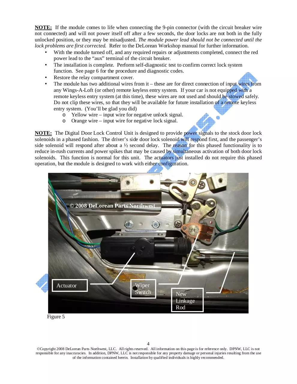
• Install the new actuator assemblies into the same bolt locations as the solenoids. Note that
the actuator assemblies are opposite for right and left hand doors. Figure 5 shows the left
hand actuator and bracket installed; Figure 6 shows the actuator in place and linkage
attached. The appearance of the components shown may vary from the components supplied.
• Manually cycle both the lock mechanism and new actuator back and forth, and tighten the
parallel rod clamp so that the actuator stops slightly before the end of its stroke with the
locking bell crank in the fully retracted or “unlock” position.
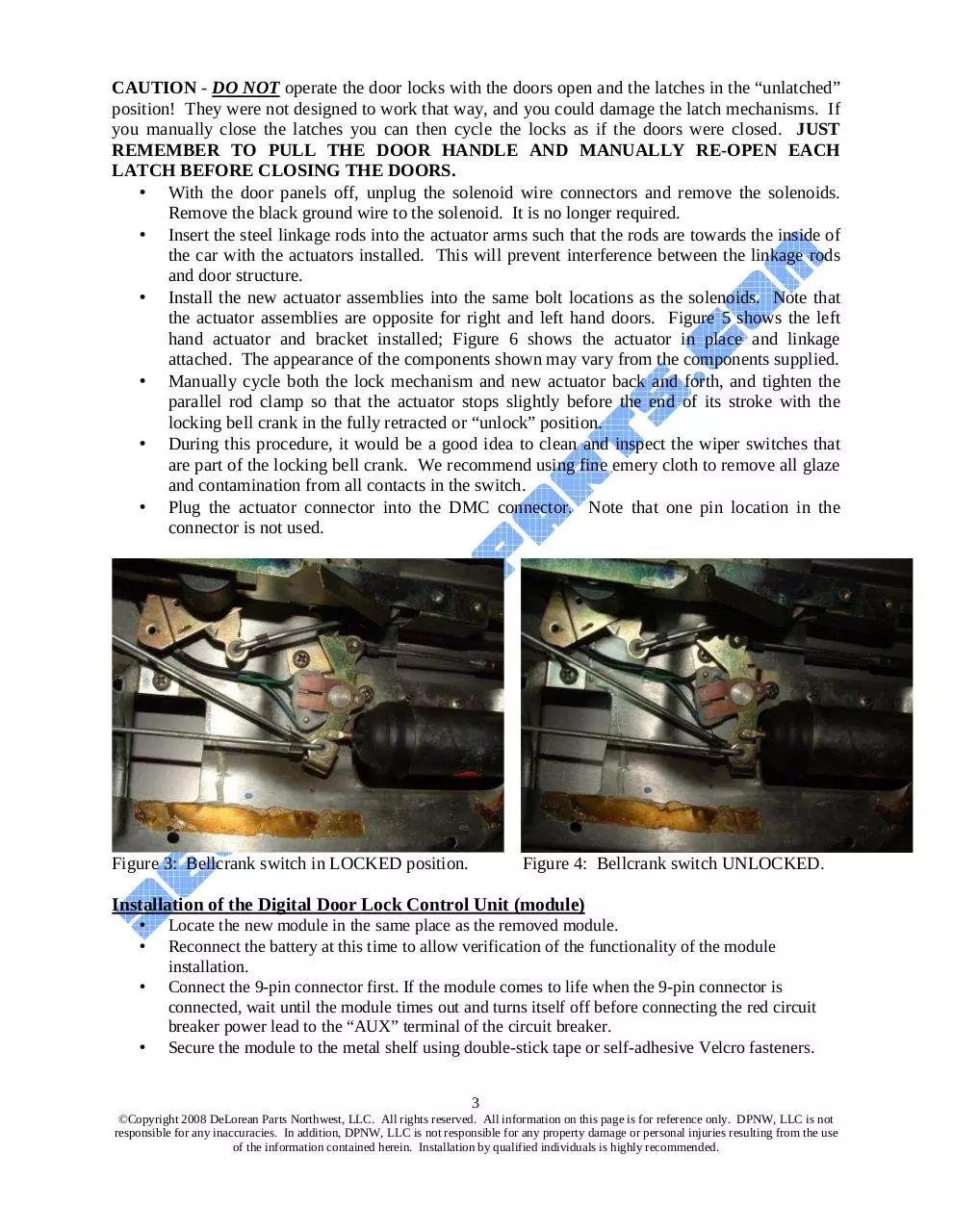
• During this procedure, it would be a good idea to clean and inspect the wiper switches that
are part of the locking bell crank. We recommend using fine emery cloth to remove all glaze
and contamination from all contacts in the switch.
• Plug the actuator connector into the DMC connector. Note that one pin location in the
connector is not used.
Figure 3: Bellcrank switch in LOCKED position.
Figure 4: Bellcrank switch UNLOCKED.
Installation of the Digital Door Lock Control Unit (module)
•
•
•
•
Locate the new module in the same place as the removed module.
Reconnect the battery at this time to allow verification of the functionality of the module
installation.
Connect the 9-pin connector first. If the module comes to life when the 9-pin connector is
connected, wait until the module times out and turns itself off before connecting the red circuit
breaker power lead to the “AUX” terminal of the circuit breaker.
Secure the module to the metal shelf using double-stick tape or self-adhesive Velcro fasteners.
3
©Copyright 2008 DeLorean Parts Northwest, LLC. All rights reserved. All information on this page is for reference only. DPNW, LLC is not
responsible for any inaccuracies. In addition, DPNW, LLC is not responsible for any property damage or personal injuries resulting from the use
of the information contained herein. Installation by qualified individuals is highly recommended.
NOTE: If the module comes to life when connecting the 9-pin connector (with the circuit breaker wire
not connected) and will not power itself off after a few seconds, the door locks are not both in the fully
unlocked position, or they may be misadjusted. The module power lead should not be connected until the
lock problems are first corrected. Refer to the DeLorean Workshop manual for further information.
• With the module turned off, and any required repairs or adjustments completed, connect the red
power lead to the “aux” terminal of the circuit breaker.
• The installation is complete. Perform self-diagnostic test to confirm correct lock system
function. See page 6 for the procedure and diagnostic codes.
• Restore the relay compartment cover.
• The module has two additional wires from it – these are for direct connection of input wires from
any Wings-A-Loft (or other) remote keyless entry system. If your car is not equipped with a
remote keyless entry system (at this time), these wires are not used and should be stowed safely.
Do not clip these wires, so that they will be available for future installation of a remote keyless
entry system. (You’ll be glad you did)
o Yellow wire – input wire for negative unlock signal.
o Orange wire – input wire for negative lock signal.
NOTE: The Digital Door Lock Control Unit is designed to provide power signals to the stock door lock
solenoids in a phased fashion. The driver’s side door lock solenoid will respond first, and the passenger’s
side solenoid will respond after about a ½ second delay. The reason for this phased functionality is to
reduce in-rush currents and power spikes that may be caused by simultaneous activation of both door lock
solenoids. This function is normal for this unit. The actuators just installed do not require this phased
operation, but the module is designed to work with either configuration.
© 2008 DeLorean Parts Northwest
Actuator
Wiper
Switch
New
Linkage
Rod
Figure 5
4
©Copyright 2008 DeLorean Parts Northwest, LLC. All rights reserved. All information on this page is for reference only. DPNW, LLC is not
responsible for any inaccuracies. In addition, DPNW, LLC is not responsible for any property damage or personal injuries resulting from the use
of the information contained herein. Installation by qualified individuals is highly recommended.
New Linkage
Rod
© 2008 DeLorean
Parts Northwest
Actuator
Parallel
Rod Clamp
DMC Lock
Rod
Figure 6
See the following pages for a guide to operating indicators and tone signals, and a guide to
the self-diagnostic test indicators and tone signals
•
NOTE: Please retain these instructions for future reference.
SPECIAL NOTE: The Series 3 version of the Digital Door Lock Control Unit has two fuses
incorporated onto the internal printed circuit board. These fuses are designed to provide overload
protection for the module in the event that there is a fault in the DeLorean wiring or locking mechanism
that may create a power surge or feedback into the module upon installation. If the module fails to
perform when installed according to these instructions, these fuses should be checked to see if they have
blown.
To visually check these two fuses, carefully remove the top cover of the module to reveal the internal
printed circuit board and electronics. The fuses are located at the end of the circuit board on either side of
the main wire bundle that exits the module.
If either of the fuses is blown, this indicates that there is a fault in the DeLorean wiring that must be
corrected before the module can be used. Failure to correct serious faults in the DeLorean wiring or door
locking mechanisms may result in damage to the module. You are encouraged to contact the vendor that
supplied you with the Digital Door Lock Control Unit for further guidance. After correcting any faults,
the fuse(s) must be replaced before the module will operate properly.
5
©Copyright 2008 DeLorean Parts Northwest, LLC. All rights reserved. All information on this page is for reference only. DPNW, LLC is not
responsible for any inaccuracies. In addition, DPNW, LLC is not responsible for any property damage or personal injuries resulting from the use
of the information contained herein. Installation by qualified individuals is highly recommended.
Operating Indicators
Or
Are Flashing LED’s
Executing unlock
sequence
Executing lock
sequence
Drivers unlock
solenoid energized.
Drivers lock
solenoid energized.
Passengers unlock
solenoid energized.
Passengers lock
solenoid energized.
Sequence
successful.
Sequence
successful.
Unlock failed. Unit
will perform a
reversing attempt.
Lock failed. Unit
will perform a
reversing attempt.
6
©Copyright 2008 DeLorean Parts Northwest, LLC. All rights reserved. All information on this page is for reference only. DPNW, LLC is not
responsible for any inaccuracies. In addition, DPNW, LLC is not responsible for any property damage or personal injuries resulting from the use
of the information contained herein. Installation by qualified individuals is highly recommended.
Self-Test Diagnostics
After installing the module according to the installation instructions, the module can perform
a complete diagnostic test of the door lock solenoids (or actuators) and the bellcrank linkages.
Ensure both doors are unlocked, both doors are latched (either by closing both doors or
manually tripping the door latches), and the unit is connected and quiet.
Press and hold the test button on the module for several seconds and then release. After a
moment, the module will proceed with a complete door lock diagnostic sequence. If the
module finds both door locks in proper operating condition, the module will end the sequence
with a green LED three flash acknowledgement and power itself off. If the module detects a
problem, it will display one of the diagnostic codes below. The door lock fault must be
corrected before the module can be used. Disconnect the module until you have corrected the
fault, and confirm the fix by repeating the self-diagnostic test procedure.
Indicators Flashing Together
Indicators Flashing Alternating
Test fault before starting. One of
the door bellcranks is not unlocked
and is touching the locked
position. Both doors must be
unlocked at start of test.
Test fault after locking both
doors. One of the door
bellcranks is not locked and
is touching the unlocked
position.
Passenger unlock action failed
to deactivate lock bellcrank
contact.
Passenger lock action failed to
activate lock bellcrank contact.
Driver lock action failed to
activate lock bellcrank
contact.
Driver unlock action failed to
deactivate lock bellcrank
contact.
Passenger unlock action failed
to activate unlock bellcrank
contact.
Passenger lock action failed
to deactivate unlock bellcrank
contact.
Driver unlock action failed to
activate unlock bellcrank
contact.
Driver lock action failed to
deactivate unlock bellcrank
contact.
7
©Copyright 2008 DeLorean Parts Northwest, LLC. All rights reserved. All information on this page is for reference only. DPNW, LLC is not
responsible for any inaccuracies. In addition, DPNW, LLC is not responsible for any property damage or personal injuries resulting from the use
of the information contained herein. Installation by qualified individuals is highly recommended.
Module Diagnostics Overview
The digital door lock module detects and responds to lock faults and will avoid damage to the actuators or
solenoids by only sending an occasional short pulse to the actuators or solenoids. However, the module
will not go into standby until it finds a lock setting that does not have a fault. If you attempt to lock the
doors and the module senses a fault after throwing the locks, the module will perform a back off by
unlocking the doors in order to attempt to avoid leaving the locks in a fault condition. The module will
not correct lock linkage problems, wiring faults, or solenoid problems.
The module is energized as a result of the door lock bellcranks being in opposite settings. The module can
only power down if the bellcranks on both doors are in the same setting (either locked or unlocked).
Trouble Shooting
Symptom
Possible Cause
When I lock a door, the
doors unlock themselves
after a couple seconds.
One of the door locks is not registering as being locked after the lock sequence,
causing the module to clear the fault by unlocking the doors. This is typically due
to linkage misadjustment on either (or both) locks which prevents the full throw of
the action, or is due to a failed lock coil on either of the solenoids. See Fault
Isolation & Diagnostics instructions.
When I unlock a door, the One of the door locks is not registering as being unlocked after the unlock
doors lock themselves after sequence, causing the module to clear the fault by throwing the locks back to the
a couple seconds.
fault-free locked position. This is typically due to linkage misadjustment on either
(or both) locks which prevents the full throw of the action, or is due to a failed
unlock coil on either of the solenoids. See Fault Isolation & Diagnostics
instructions.
After I install the module The module is unable to find a fault-free door lock setting in either the locked or
and activate it by throwing unlocked settings. This is typically due to a severe linkage misadjustment or
a lock, the module
solenoid failures that result in poor lock performance in both the lock and unlock
repeatedly locks and
action. See Fault Isolation & Diagnostics instructions.
unlocks the doors every few
seconds.
Fault Isolation & Diagnostics
The fault isolation procedure refers to some of the diagnostic indicators identified in the previous
table. Position the module so you can see the indicators for the fault isolation procedure. Since
locking/unlocking the doors should only be done with the doors closed, it is most convenient to
perform the operations from the driver’s seat while looking over into the relay compartment at the
module’s indicators.
NOTE – The following procedures are written for basic diagnostics with solenoids installed.
After the DPNW actuators have been installed to replace the solenoids, simply replace the word
“solenoid” with “actuator”. The diagnostic procedures would be similar.
8
©Copyright 2008 DeLorean Parts Northwest, LLC. All rights reserved. All information on this page is for reference only. DPNW, LLC is not
responsible for any inaccuracies. In addition, DPNW, LLC is not responsible for any property damage or personal injuries resulting from the use
of the information contained herein. Installation by qualified individuals is highly recommended.
Step
1
2
3
4
5
6
Diagnostic
Disconnect the lone
The module may come to life briefly but should power off after a couple seconds. If
power lead for the
the module comes to life and then powers down, the last sequence it performs before
module but leave the powering down should be the unlock sequence (see diagnostic indicators). If it does
main wiring harness not power down, one of the door lock linkages is misadjusted and one of the
connector attached.
bellcranks is touching the lock sense contacts even in the unlocked position.
Manually put both
door locks in the
unlocked position
using the lock/unlock
buttons on each door.
Manually put the
The module should come to life and continually cycle without shutting down. If the
driver’s door lock in module powers off and the last sequence executed before it turns off is the lock
the locked position and sequence, the linkage for the passenger door lock is misadjusted. If the module
put the passenger door powers off and the last sequence executed before it turns off is the unlock sequence,
lock in the unlocked the linkage for the driver’s door is misadjusted.
position using the
lock/unlock buttons on
each door.
Manually put the
The module should come to life and continually cycle without shutting down. If the
driver’s door lock in module powers off and the last sequence executed before it turns off is the lock
the unlocked position sequence, the linkage for the driver’s door is misadjusted. If the module powers off
and put the passenger and the last sequence executed before it turns off is the unlock sequence, the linkage
door lock in the locked for the passenger’s door is misadjusted.
position using the
lock/unlock buttons on
each door.
Manually put both
The module should come to life briefly and then power off after a couple seconds.
door locks in the
The last sequence it should perform before powering down is the lock sequence. If it
locked position using does not power down, one of the door lock linkages is misadjusted and one of the
the lock/unlock buttons bellcranks is touching the unlock sense contacts even in the locked position.
on each door.
Proceed with the
following steps only if
steps 1-4 all check out.
Manually put both
door locks in the
unlocked position and
then plug in the
module’s power lead.
Lock the driver’s door
using the lock/unlock
button.
If the module comes to life, disconnect the power lead and start over with step 1.
If the module does not come to life, start over with step 1. If the passenger door lock
is not thrown, the passenger solenoid lock coil is defective. If the passenger lock is
thrown, but the module reverses the locks after a couple seconds, then the passenger
solenoid is weak or the passenger linkage is misadjusted so that the lock is not
thrown far enough through its range of motion. You can confirm a weak solenoid or
linkage misadjustment of the passenger locking action by doing this step again but
help the passenger lock along by pushing the passenger lock button after the solenoid
engages it. If helping the locking action along causes the lock sequence to complete
successfully, the problem is confirmed.
9
©Copyright 2008 DeLorean Parts Northwest, LLC. All rights reserved. All information on this page is for reference only. DPNW, LLC is not
responsible for any inaccuracies. In addition, DPNW, LLC is not responsible for any property damage or personal injuries resulting from the use
of the information contained herein. Installation by qualified individuals is highly recommended.
Download Digital Door Lock Module & Actuators
Digital Door Lock Module & Actuators.pdf (PDF, 562.68 KB)
Download PDF
Share this file on social networks
Link to this page
Permanent link
Use the permanent link to the download page to share your document on Facebook, Twitter, LinkedIn, or directly with a contact by e-Mail, Messenger, Whatsapp, Line..
Short link
Use the short link to share your document on Twitter or by text message (SMS)
HTML Code
Copy the following HTML code to share your document on a Website or Blog
QR Code to this page

This file has been shared publicly by a user of PDF Archive.
Document ID: 0000162811.