HIOKI 3245 60 ENG (PDF)
File information
Title: HiTESTER series 3244-60/3245-60/3246-60/3030-10/3008/3258
Author: HIOKI
This PDF 1.6 document has been generated by Adobe InDesign CS5.5_J (7.5.3) / Adobe PDF Library 9.9, and has been sent on pdf-archive.com on 24/12/2015 at 15:40, from IP address 5.18.x.x.
The current document download page has been viewed 533 times.
File size: 3.16 MB (3 pages).
Privacy: public file

File preview
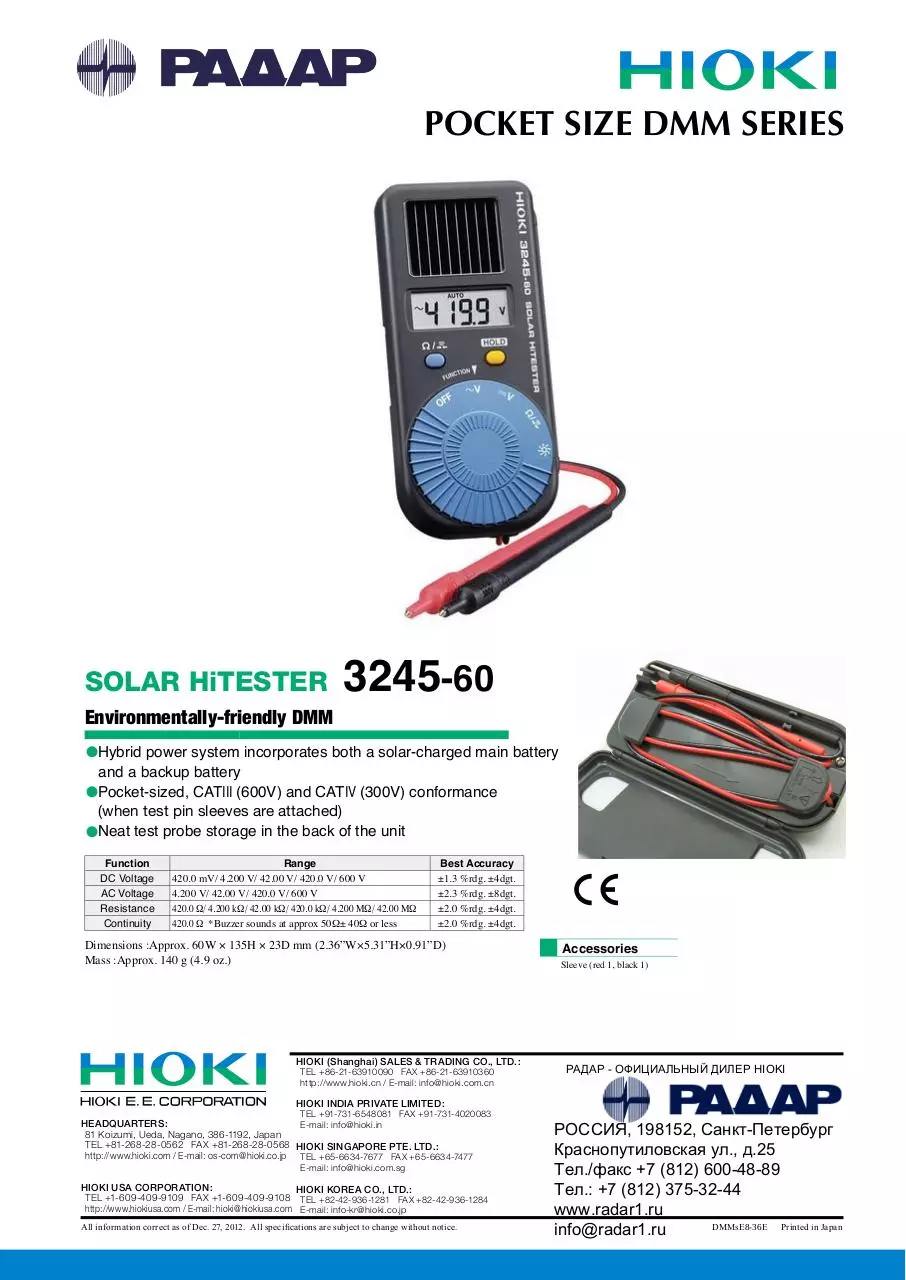
POCKET SIZE DMM SERIES
SOLAR HiTESTER
Environmentally-friendly DMM
3245-60
lHybrid power system incorporates both a solar-charged main battery
and a backup battery
lPocket-sized, CATIII (600V) and CATIV (300V) conformance
(when test pin sleeves are attached)
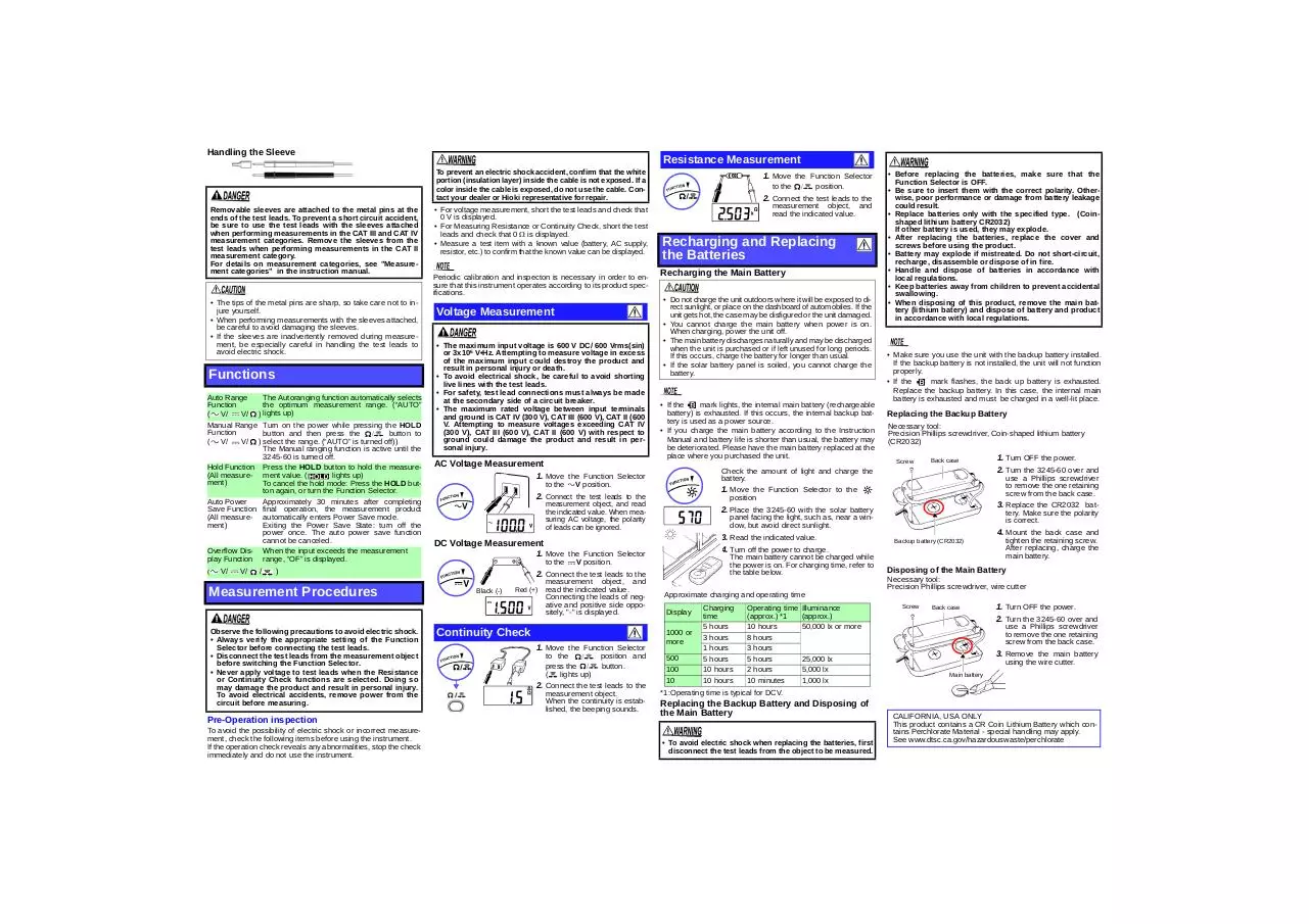
lNeat test probe storage in the back of the unit
Function
DC Voltage
AC Voltage
Resistance
Continuity
Range
420.0 mV/ 4.200 V/ 42.00 V/ 420.0 V/ 600 V
4.200 V/ 42.00 V/ 420.0 V/ 600 V
420.0 W/ 4.200 kW/ 42.00 kW/ 420.0 kW/ 4.200 MW/ 42.00 MW
420.0 W *Buzzer sounds at approx 50W± 40W or less
Best Accuracy
±1.3 %rdg. ±4dgt.
±2.3 %rdg. ±8dgt.
±2.0 %rdg. ±4dgt.
±2.0 %rdg. ±4dgt.
Dimensions :Approx. 60W × 135H × 23D mm (2.36”W×5.31”H×0.91”D)
Mass :Approx. 140 g (4.9 oz.)
HIOKI (Shanghai) SALES & TRADING CO., LTD.:
TEL +86-21-63910090 FAX +86-21-63910360
http://www.hioki.cn / E-mail: info@hioki.com.cn
Accessories
Sleeve (red 1, black 1)
РАДАР - ОФИЦИАЛЬНЫЙ ДИЛЕР HIOKI
HIOKI INDIA PRIVATE LIMITED:
TEL +91-731-6548081 FAX +91-731-4020083
HEADQUARTERS:
E-mail: info@hioki.in
81 Koizumi, Ueda, Nagano, 386-1192, Japan
TEL +81-268-28-0562 FAX +81-268-28-0568 HIOKI SINGAPORE PTE. LTD.:
http://www.hioki.com / E-mail: os-com@hioki.co.jp TEL +65-6634-7677 FAX +65-6634-7477
E-mail: info@hioki.com.sg
HIOKI USA CORPORATION:
HIOKI KOREA CO., LTD.:
TEL +1-609-409-9109 FAX +1-609-409-9108 TEL +82-42-936-1281 FAX +82-42-936-1284
http://www.hiokiusa.com / E-mail: hioki@hiokiusa.com E-mail: info-kr@hioki.co.jp
All information correct as of Dec. 27, 2012. All specifications are subject to change without notice.
РОССИЯ, 198152, Санкт-Петербург
Краснопутиловская ул., д.25
Тел./факс +7 (812) 600-48-89
Тел.: +7 (812) 375-32-44
www.radar1.ru
DMMsE8-36E Printed in Japan
info@radar1.ru
Measurement categories
3245-60
SOLAR HiTESTER
Instruction Manual
September 2013 Revised edition 4
Printed in Japan
3245C981-04 13-09H
(3245-61)
This product complies with CAT IV (300 V), CAT III (600 V), CAT II (600 V)
safety requirements.
To ensure safe operation of measurement products, IEC 61010 establishes
safety standards for various electrical environments, categorized as CAT II to
CAT IV, and called measurement categories.
CAT II: Primary electrical circuits in
equipment connected to an AC electrical outlet by a power cord (portable tools, household appliances,
etc.). CAT II covers directly measuring electrical outlet receptacles.
CAT III: Primary electrical circuits
of heavy equipment (fixed installations) connected directly to the distribution panel, and feeders from
the distribution panel to outlets.
CAT IV: The circuit from the service drop to the service entrance, and to the
power meter and primary overcurrent protection device (distribution panel).
Using a measurement instrumentin an environment designated with a highernumbered category than that for which the instrument is rated could result in a
severe accident, and must be carefully avoided. Use of a measurement instrument that is not CAT-rated in CAT II to CAT IV measurement applications could
result in a severe accident, and must be carefully avoided.
Safety Symbol
In the manual, the
symbol indicates particularly important
information that the user should read before using the product.
The
symbol printed on the product indicates that the user
should refer to a corresponding topic in the manual (marked
with the
symbol) before using the relevant function.
Indicates a double-insulated device.
Indicates AC (Alternating Current).
• If the protective functions of the product are damaged, either
remove it from service or mark it clearly so that others do not
use it inadvertently.
• The solar battery and the liquid crystal display are made of
glass. In order to avoid damage to the product or injury to the
user, do not strike, drop, or apply excess pressure to them.
• Accurate measurement may be impossible in the presence of
strong magnetic fields, such as near transformers and highcurrent conductors, or in the presence of strong electromagnetic fields such as near radio transmitters.
• When not in use, store the unit in a well-lit location rather than
in a container such as a toolbox.
• To avoid battery depletion, turn the Function Selector OFF
after use (the Auto Power Save feature consumes a small
amount of current).
• The
indicator appears when main battery voltage
becomes low. Charge the battery as soon as possible.
• The
indicator appears (flashes) when backup battery voltage becomes low. Replace the batteries as soon as possible.
• To avoid corrosion from battery leakage, remove the batteries
from the product if it is to be stored for a long time.
• Batteries are not included in the basic price of the 3245-60.
(For testing purposes, a battery is inserted into the product, but
if this should be exhausted it is not replaced free of charge.)
Indicates DC (Direct Current).
Warranty
Warranty malfunctions occurring under conditions of normal use in conformity with the Instruction Manual and Product Precautionary Markings will be repaired free of charge. This warranty is valid for a period
of three (3) years from the date of purchase. Please contact the distributor from which you purchased the product for further information on
warranty provisions.
Introduction
Thank you for purchasing the HIOKI “3245-60 SOLAR HiTESTER”. To obtain maximum performance from the product,
please read this manual first, and keep it handy for future reference.
Initial Inspection
When you receive the product, inspect it carefully to ensure
that no damage occurred during shipping. If damage is evident,
or if it fails to operate according to the specifications, contact
your dealer or Hioki representative.
Preliminary Checks
• Before using the product the first time, verify that it operates
normally to ensure that the no damage occurred during storage or shipping. If you find any damage, contact your dealer
or Hioki representative.
Maintenance and Service
• To clean the product, wipe it gently with a soft cloth moistened with water or mild detergent. Never use solvents such
as benzene, alcohol, acetone, ether, ketones, thinners or
gasoline, as they can deform and discolor the case.
• If the product seems to be malfunctioning, confirm that the
batteries are not discharged, and contact your dealer or Hioki
representative.
Safety
Follow these precautions to ensure safe operation and to obtain
the full benefits of the various functions.
This instrument is designed to comply with IEC 61010
Safety Standards, and has been thoroughly tested for
safety prior to shipment. However, mishandling during
use could result in injury or death, as well as damage to
the instrument Using the instrument in a way not
described in this manual may negate the provided safety
features. Be certain that you understand the instructions
and precautions in the manual before use. We disclaim
any responsibility for accidents or injuries not resulting
directly from instrument defects.
Symbols for Various Standards
This symbol indicates that the product conforms to safety regulations set out by the EC Directive.
WEEE marking:
This symbol indicates that the electrical and electronic appliance is
put on the EU market after August 13, 2005, and producers of the
Member States are required to display it on the appliance under
Article 11.2 of Directive 2002/96/EC (WEEE).
The following symbols in this manual indicate the relative importance
of cautions and warnings.
Indicates that incorrect operation presents an extreme hazard that could result in serious injury or death to the user.
Indicates that incorrect operation presents a significant hazard that could result in serious injury or death to the user.
Indicates that incorrect operation presents a possibility of
injury to the user or damage to the product.
Advisory items related to performance or correct operation
of the product.
Usage Notes
This manual contains information and warnings essential for
safe operation of the product and for maintaining it in safe
operating condition. Before using the product, be sure to carefully read the following safety notes.
To avoid electric shock when measuring live lines, wear
appropriate protective gear, such as insulated rubber
gloves, boots and a safety helmet.
• Do not store or use the product where it could be exposed
to direct sunlight, high temperature or humidity, or condensation. Under such conditions, the product may be damaged
and insulation may deteriorate so that it no longer meets
specifications.
• This product is not designed to be entirely water- or dust-proof.
To avoid damage, do not use it in a wet or dusty environment.
• To avoid damage to the product, protect it from vibration or
shock during transport and handling, and be especially careful to avoid dropping.
When sleeve is installed :CAT IV(300 V), CAT III (600 V)
When sleeve is uninstalled: CAT II (600 V)
(Anticipated Transient Overvoltage: 6000 V)
15 mVA
Maximum rated
voltage to earth
Specifications
Rated Power
Accuracy (Accuracy guaranteed for one year at 23±5°C (73±9°F),
80%RH or less.) Battery low display
DC Voltage
Measurement
(DCV)
AC Voltage
Measurement
(ACV)
Resistance
Measurement
()
Continuity
Check (
)
420.0
Light check
4200
Function
Additional
Function
Display
Range Switching
Sampling Rate
Power Supply
Battery-Life
Warning
Dimensions
Parts Names
Dual integration
Test Leads
Red (+)
Black ()
Average rectifying measurement
DC voltage (DCV), AC voltage(ACV), Resistance (),
Continuity check( ), Light check
Auto Range function, Manual Range function,
Hold function, Auto Power Save function (APS),
Overflow Warning function, Battery-Life Warning function
TN type LCD, 1/4 duty, dynamic drive
Max. 4199 counts
Auto-range, manual range
2.5 S/s
Main battery:
Rechargeable lithium battery
Backup battery: Coin-shaped lithium battery,
CR2032 (3VDC) × 1
Main battery exhausted:
lights (accuracy assured)
Backup battery exhausted:
flashes (accuracy not assured)
Approx. 60W ×135H ×23D mm (without protrusions)
(2.36“W × 5.31“H × 0.91“D)
Cable length:Approx. 520 mm (20.47”)
Approx.140 g (4.9 oz.) (including batteries)
Electrical Characteristics
Dielectric strength
Notes
100 M or more
Approx.11 M
±1.3%rdg.±4dgt. Approx.10 M
Approx.10 M
Approx.10 M
Approx. 11 M
±2.3%rdg.±8dgt. Approx. 10 M
(50 to 500 Hz)
Approx. 10 M
Approx. 10 M
±2.0%rdg.±4dgt. 3.4V or less.
±2.0%rdg.±4dgt. 0.7 V typ.
±2.0%rdg.±4dgt. 0.5 V typ.
±2.0%rdg.±4dgt. 0.5 V typ.
±5.0%rdg.±4dgt. 0.5 V typ.
±10.0%rdg.±4dgt. 0.5 V typ.
3.4V or less
±2.0%rdg.±4dgt. Threshold level (buzzer sounds)
: 50±40
“1000” is displayed at approx.
50,000lx
Solar Battery Panel
Mass
Operating
up to 2000 m (6562-ft.) ASL,Indoors, Pollution Degree 2
Environment
Operating Tempera- 0 to 40°C (32 to 104°F), at 80%RH or less
ture & Humidity
(non-condensating)
Storage Temperature -20 to 50°C (-4 to 122°F), at 70%RH or less
& Humidity
(non-condensating)
Instruction Manual, carrying case, Coin-shaped lithium
Accessories
battery (CR2032) x1 (supplied with this product for monitor), Sleeves (red and black 1 piece for each)
Applicable
Safety EN61010
Standards
EMC EN61326
Temperature
Characteristic
Noise Suppression
(50/60Hz)
Operating time and
charging time
Backup battery life
is not flash.
Accuracy
Overload protection is 600V DC/AC rms (sine wave) or 3x10⁶ VHz (for 1 min.),
for all functions and ranges.
dgt.: resolution (The smallest displayable unit, i.e., the input value that causes
the digital display to show a "1".)
rdg.: reading value (The value currently being measured and indicated on the
measuring product)
General
Measurement
Method
AC Measurement
System
Range
420.0 mV
4.200 V
42.00 V
420.0 V
600 V
4.200 V
42.00 V
420.0 V
600 V
420.0
4.200 k
42.00 k
420.0 k
4.200 M
42.00 M
Measurement accuracy x 0.1 /C (except 23C±5C)
NMRR:40dB or better(DCV)
CMRR:100dB or better(DCV), 60dB or better(ACV)
8 hours when charged for 3 hours at about 50,000 lx
(DCV)
Approx. 150 hours (DCV, continuous)
5550 Vrms sin (50/60Hz for one minute),
between input and case
Maximum input Voltage600 VDC/ 600 Vrms (sin) or 3 ×10⁶VHz
LCD Display
HOLD Button
Holds the
measurement value
(
lights
up)
Button
Switches the
and
function.
Function Selector
Off (Power is turned ON in any position other
OFF Power
than OFF.)
V AC voltage function (ACV)
Resistance function
Continuity Check
V DC voltage function (DCV)
function
Light meter
Using the Test Lead Holder
Use the test lead holder to secure the test lead probe in place.
Rear cover
Test lead holder
1. Open the rear cover.
2. Unwind the extra lead.
3. Insert the test lead
probe into the test lead
holder.
4. Shut the rear cover.
Handling the Sleeve
Removable sleeves are attached to the metal pins at the
ends of the test leads. To prevent a short circuit accident,
be sure to use the test leads with the sleeves attached
when performing measurements in the CAT III and CAT IV
measurement categories. Remove the sleeves from the
test leads when performing measurements in the CAT II
measurement category.
For details on measurement categories, see "Measurement categories" in the instruction manual.
• The tips of the metal pins are sharp, so take care not to injure yourself.
• When performing measurements with the sleeves attached,
be careful to avoid damaging the sleeves.
• If the sleeves are inadvertently removed during measurement, be especially careful in handling the test leads to
avoid electric shock.
Functions
Auto Range
Function
( V/
V/ )
Manual Range
Function
( V/
V/ )
The Autoranging function automatically selects
the optimum measurement range. (“AUTO”
lights up)
Turn on the power while pressing the HOLD
button and then press the
button to
select the range. (“AUTO” is turned off))
The Manual ranging function is active until the
3245-60 is turned off.
Hold Function Press the HOLD button to hold the measure(All measure- ment value. (
lights up)
ment)
To cancel the hold mode: Press the HOLD button again, or turn the Function Selector.
Auto Power
Approximately 30 minutes after completing
Save Function final operation, the measurement product
(All measure- automatically enters Power Save mode.
ment)
Exiting the Power Save State: turn off the
power once. The auto power save function
cannot be canceled.
Overflow Dis- When the input exceeds the measurement
play Function range, “OF” is displayed.
(
V/
V/
/
Resistance Measurement
To prevent an electric shock accident, confirm that the white
portion (insulation layer) inside the cable is not exposed. If a
color inside the cable is exposed, do not use the cable. Contact your dealer or Hioki representative for repair.
1. Move the Function Selector
• For voltage measurement, short the test leads and check that
0 V is displayed.
• For Measuring Resistance or Continuity Check, short the test
leads and check that 0 is displayed.
• Measure a test item with a known value (battery, AC supply,
resistor, etc.) to confirm that the known value can be displayed.
measurement object, and
read the indicated value.
Periodic calibration and inspecton is necessary in order to ensure that this instrument operates according to its product specifications.
Voltage Measurement
• The maximum input voltage is 600 V DC/ 600 Vrms(sin)
or 3x10⁶ V•Hz. Attempting to measure voltage in excess
of the maximum input could destroy the product and
result in personal injury or death.
• To avoid electrical shock, be careful to avoid shorting
live lines with the test leads.
• For safety, test lead connections must always be made
at the secondary side of a circuit breaker.
• The maximum rated voltage between input terminals
and ground is CAT IV (300 V), CAT III (600 V), CAT II (600
V. Attempting to measure voltages exceeding CAT IV
(300 V), CAT III (600 V), CAT II (600 V) with respect to
ground could damage the product and result in personal injury.
Observe the following precautions to avoid electric shock.
• Always verify the appropriate setting of the Function
Selector before connecting the test leads.
• Disconnect the test leads from the measurement object
before switching the Function Selector.
• Never apply voltage to test leads when the Resistance
or Continuity Check functions are selected. Doing so
may damage the product and result in personal injury.
To avoid electrical accidents, remove power from the
circuit before measuring.
Pre-Operation inspection
To avoid the possibility of electric shock or incorrect measurement, check the following items before using the instrument.
If the operation check reveals any abnormalities, stop the check
immediately and do not use the instrument.
Recharging and Replacing
the Batteries
Recharging the Main Battery
• Do not charge the unit outdoors where it will be exposed to direct sunlight, or place on the dashboard of automobiles. If the
unit gets hot, the case may be disfigured or the unit damaged.
• You cannot charge the main battery when power is on.
When charging, power the unit off.
• The main battery discharges naturally and may be discharged
when the unit is purchased or if left unused for long periods.
If this occurs, charge the battery for longer than usual.
• If the solar battery panel is soiled, you cannot charge the
battery.
• If the
mark lights, the internal main battery (rechargeable
battery) is exhausted. If this occurs, the internal backup battery is used as a power source.
• If you charge the main battery according to the Instruction
Manual and battery life is shorter than usual, the battery may
be deteriorated. Please have the main battery replaced at the
place where you purchased the unit.
V position.
2. Connect the test leads to the
measurement object, and read
the indicated value. When measuring AC voltage, the polarity
of leads can be ignored.
3. Read the indicated value.
4. Turn off the power to charge.
The main battery cannot be charged while
the power is on. For charging time, refer to
the table below.
V position.
2. Connect the test leads to the
Black (-)
Continuity Check
1. Move the Function Selector
to the
press the
(
lights up)
position and
button.
2. Connect the test leads to the
measurement object.
When the continuity is established, the beeping sounds.
Replacing the Backup Battery
Necessary tool:
Precision Phillips screwdriver, Coin-shaped lithium battery
(CR2032)
Screw
Back case
1. Turn OFF the power.
2. Turn the 3245-60 over and
use a Phillips screwdriver
to remove the one retaining
screw from the back case.
3. Replace the CR2032 battery. Make sure the polarity
is correct.
panel facing the light, such as, near a window, but avoid direct sunlight.
1. Move the Function Selector
measurement object, and
Red (+) read the indicated value.
Connecting the leads of negative and positive side oppositely, "-" is displayed.
• Make sure you use the unit with the backup battery installed.
If the backup battery is not installed, the unit will not function
properly.
• If the
mark flashes, the back up battery is exhausted.
Replace the backup battery. In this case, the internal main
battery is exhausted and must be charged in a well-lit place.
2. Place the 3245-60 with the solar battery
DC Voltage Measurement
to the
• Before replacing the batteries, make sure that the
Function Selector is OFF.
• Be sure to insert them with the correct polarity. Otherwise, poor performance or damage from battery leakage
could result.
• Replace batteries only with the specified type. (Coinshaped lithium battery CR2032)
If other battery is used, they may explode.
• After replacing the batteries, replace the cover and
screws before using the product.
• Battery may explode if mistreated. Do not short-circuit,
recharge, disassemble or dispose of in fire.
• Handle and dispose of batteries in accordance with
local regulations.
• Keep batteries away from children to prevent accidental
swallowing.
• When disposing of this product, remove the main battery (lithium batery) and dispose of battery and product
in accordance with local regulations.
Check the amount of light and charge the
battery.
1. Move the Function Selector to the
position
1. Move the Function Selector
to the
position.
2. Connect the test leads to the
AC Voltage Measurement
)
Measurement Procedures
to the
4. Mount the back case and
Backup battery (CR2032)
tighten the retaining screw.
After replacing, charge the
main battery.
Disposing of the Main Battery
Necessary tool:
Precision Phillips screwdriver, wire cutter
Approximate charging and operating time
Display
1000 or
more
500
100
10
Charging
time
5 hours
3 hours
1 hours
5 hours
10 hours
10 hours
Operating time
(approx.) *1
10 hours
8 hours
3 hours
5 hours
2 hours
10 minutes
Illuminance
(approx.)
50,000 lx or more
25,000 lx
5,000 lx
1,000 lx
Screw
Back case
1. Turn OFF the power.
2. Turn the 3245-60 over and
use a Phillips screwdriver
to remove the one retaining
screw from the back case.
3. Remove the main battery
using the wire cutter.
Main battery
*1:Operating time is typical for DCV.
Replacing the Backup Battery and Disposing of
the Main Battery
• To avoid electric shock when replacing the batteries, first
disconnect the test leads from the object to be measured.
CALIFORNIA, USA ONLY
This product contains a CR Coin Lithium Battery which contains Perchlorate Material - special handling may apply.
See www.dtsc.ca.gov/hazardouswaste/perchlorate
Download HIOKI 3245-60 ENG
HIOKI_3245-60_ENG.pdf (PDF, 3.16 MB)
Download PDF
Share this file on social networks
Link to this page
Permanent link
Use the permanent link to the download page to share your document on Facebook, Twitter, LinkedIn, or directly with a contact by e-Mail, Messenger, Whatsapp, Line..
Short link
Use the short link to share your document on Twitter or by text message (SMS)
HTML Code
Copy the following HTML code to share your document on a Website or Blog
QR Code to this page

This file has been shared publicly by a user of PDF Archive.
Document ID: 0000326479.