Article CellaCast 201301 en (PDF)
File information
This PDF 1.6 document has been generated by / PDF-XChange (xcpro40.dll v4.0.0166.0000) (Windows), and has been sent on pdf-archive.com on 12/04/2016 at 19:50, from IP address 50.192.x.x.
The current document download page has been viewed 330 times.
File size: 1.32 MB (3 pages).
Privacy: public file

File preview
Optical measurement of liquid metal temperatures
Summary
Temperature is one of the most
critical process parameters affecting the resulting quality,
strength and working properties
of a metal casting. Thanks to
modern infrared thermometers,
the temperature of molten metal
can be accurately monitored continuously and without contact at
various stages of production. The
benefits: non-contact temperature detection requires far less
use of immersion probes and
results in reduced scrap.
Disadvantages of previous
temperature measurement
techniques
The temperature of liquid metal
is commonly measured using
thermocouples (Photo 1). The
probe is dipped into the melt.
Data accuracy is subject to the
precision with which the foundry operator performs the measurement. Temperature readings will vary, depending on
the immersion depth and the
position of the probe. A slag
deposit on the sensor element
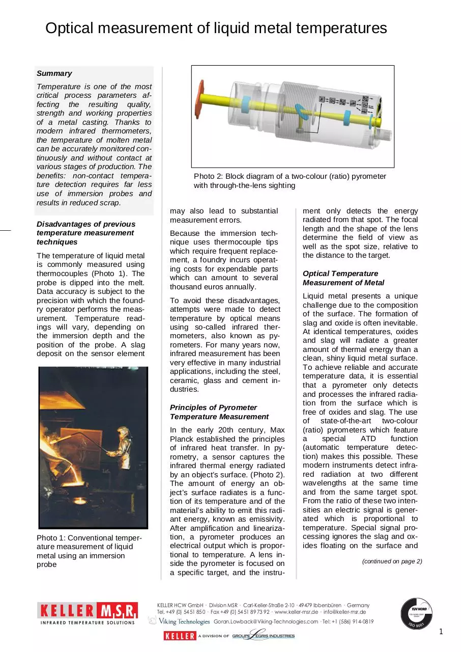
Photo 2: Block diagram of a two-colour (ratio) pyrometer
with through-the-lens sighting
may also lead to substantial
measurement errors.
Because the immersion technique uses thermocouple tips
which require frequent replacement, a foundry incurs operating costs for expendable parts
which can amount to several
thousand euros annually.
To avoid these disadvantages,
attempts were made to detect
temperature by optical means
using so-called infrared thermometers, also known as pyrometers. For many years now,
infrared measurement has been
very effective in many industrial
applications, including the steel,
ceramic, glass and cement industries.
Principles of Pyrometer
Temperature Measurement
Photo 1: Conventional temperature measurement of liquid
metal using an immersion
probe
In the early 20th century, Max
Planck established the principles
of infrared heat transfer. In pyrometry, a sensor captures the
infrared thermal energy radiated
by an object’
s surface. (Photo 2).
The amount of energy an object’
s surface radiates is a function of its temperature and of the
material’
s ability to emit this radiant energy, known as emissivity.
After amplification and linearization, a pyrometer produces an
electrical output which is proportional to temperature. A lens inside the pyrometer is focused on
a specific target, and the instru-
ment only detects the energy
radiated from that spot. The focal
length and the shape of the lens
determine the field of view as
well as the spot size, relative to
the distance to the target.
Optical Temperature
Measurement of Metal
Liquid metal presents a unique
challenge due to the composition
of the surface. The formation of
slag and oxide is often inevitable.
At identical temperatures, oxides
and slag will radiate a greater
amount of thermal energy than a
clean, shiny liquid metal surface.
To achieve reliable and accurate
temperature data, it is essential
that a pyrometer only detects
and processes the infrared radiation from the surface which is
free of oxides and slag. The use
of state-of-the-art two-colour
(ratio) pyrometers which feature
a
special
ATD
function
(automatic temperature detection) makes this possible. These
modern instruments detect infrared radiation at two different
wavelengths at the same time
and from the same target spot.
From the ratio of these two intensities an electric signal is generated which is proportional to
temperature. Special signal processing ignores the slag and oxides floating on the surface and
(continued on page 2)
KELLER HCW GmbH · Division MSR · Carl-Keller-Straße 2-10 · 49479 Ibbenbüren · Germany
Tel. +49 (0) 54 51 85 0 · Fax +49 (0) 54 51 89 73 92 · www.keller-msr.de · info@keller-msr.de
Goran.Lowback@Viking-Technologies.com · Tel: +1 (586) 914-0819
1
(continued from page 1)
filters out the temperature detected from the pure liquid metal.
In harsh industrial environments
ratio pyrometers are preferred
over
spectral
or
singlewavelength pyrometers because
the dual wavelength technique is
much less sensitive to signal attenuation caused by dust or
steam in the field of view.
Different systems for various
points of measurement
Steel mills and foundries require
temperature control at numerous
manufacturing stages. Each of
these molten metal applications
presents a distinct challenge for a
temperature measurement system.
Blast furnace and cupola
furnace
At the passage where liquid metal
is transferred from the blast furnace/cupola furnace to the forehearth, temperature is typically
measured at irregular intervals by
means of a thermocouple. In contrast, pyrometers detect temperature continuously (Photo 3).
Thus, the foundry operator can
immediately intervene in the melting process, if necessary. On-site
oxide, producing extremely reliable temperature data. Through-the
-lens sighting or a laser spot light
facilitate aiming and indicate the
exact spot. More recently, pyrometers can also come equipped
with a built-in video camera which
enable continuous remote monitoring from the control room.
Melting furnace and
forehearth
Temperature is of crucial importance as the molten metal
passes from the melting furnace
or forehearth to the transfer ladle
or pouring ladle (Photo 4). The
liquid metal must be poured into
the mold within a limited time to
minimize heat loss. When cooling
exceeds 10 °C per minute, the
minimum permissible pouring temperature might be violated. Because this application requires
some distance between the instrument and the point of measurement, pyrometers with superior
optical resolution and a circular
field of view are used. The ATD
function not only filters out the
infrared radiation from slag and
oxides, it also automatically detects the start and end of each
pour. When the ladle has finished
pouring, the temperature data is
displayed and transmitted to a
data communications network.
Alternatively, data can be logged
and archived by CellaMevis standalone PC software. CellaMevis
provides online graphic images of
temperature readings at a PC and
saves them at periodic intervals
with a timestamp.
Automated casting machine
Photo 3: Measurement at the tap
hole of a blast furnace, carried
out at considerable distance
conditions require that a pyrometer be installed at a considerable
distance to the target. This is possible if the instrument features
high-resolution optics and superior
imaging properties. With smaller
target spots, the pyrometer can
easily identify and ignore slag and
The temperature of the liquid metal at the time of pouring is crucial
to the quality of the casting. If the
melt is too hot, the sand core will
be damaged. If the melt is not hot
enough, the fluidity will be inadequate, and the liquid might not
distribute properly within the mold.
This is especially true for thinwalled or intricately shaped castings. There is the risk of casting
defects such as shrink holes and
cold shut. The stability and
strength of the manufactured
workpiece as well as its subse-
Photo 4: Transfer of molten
iron from the melting furnace
into the pouring ladle
quent working properties will be
greatly influenced by the pouring
temperature. Therefore, it is absolutely essential that temperatures
at this point in the process are
accurately detected and precisely
controlled.
At fully automated casting lines,
temperature is commonly controlled by infrequent immersion of
the probe into the melt. At semiautomated operations, the temperature of the liquid metal is usually
only measured once for each newly filled ladle. The thermocouple is
dipped into the ladle before pouring begins, that is, before the
molds are filled. Depending on the
number of castings poured from
one ladle, there may be a considerable time offset between ladle
temperature measurement and
the last mold filled from the content of that ladle.
The ladle operator decides how
many castings can be poured from
one ladle, basing his decision on
the flow behavior of the melt and
his empirical knowledge of heat
loss and cooling time. Actual temperature tests using measurement
instrumentation – to assure that
the required process temperature
is maintained right down to the
last filled mold— is rarely performed.
With optical temperature detection
at metal casting operations, a pyrometer is focused on the free
(continued on page 3)
KELLER HCW GmbH · Division MSR · Carl-Keller-Straße 2-10 · 49479 Ibbenbüren · Germany
Tel. +49 (0) 54 51 85 0 · Fax +49 (0) 54 51 89 73 92 · www.keller-msr.de · info@keller-msr.de
Goran.Lowback@Viking-Technologies.com · Tel: +1 (586) 914-0819
2
(continued from page 2)
Photo 5: Optical temperature
detection at a casting machine
falling liquid metal stream just as it
is poured into the mold (Photo 5).
The ATD function automatically
identifies when the pour begins
and adapts the measuring time to
the duration of the pour stream.
A temperature reading is produced for each cast workpiece,
providing continuous verification
of compliance with temperature
requirements.
If, for example, operations are
disrupted due to a functional disturbance, and during this time, the
liquid metal in the ladle cools to
below the minimum permissible
temperature, production can be
halted to avoid producing castings
which would end up as scrap.
The challenge of temperature
detection at casting machines
Compounding the problem: the
position of the liquid metal pour
stream fluctuates. The pouring
point is influenced by factors such
as the tilt angle of the ladle or the
stopper rod in the tapping hole of
bottom pour ladles (Photo 6).
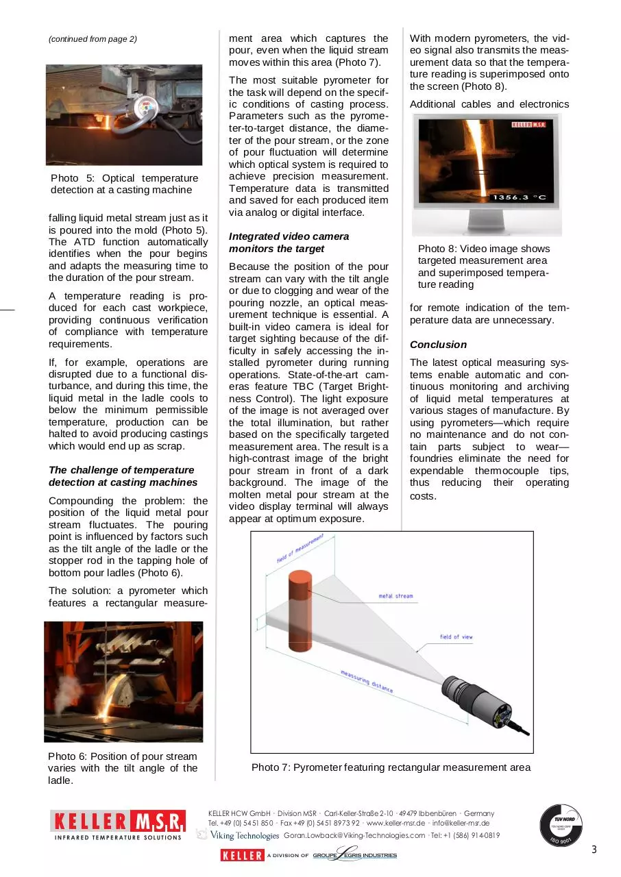
ment area which captures the
pour, even when the liquid stream
moves within this area (Photo 7).
The most suitable pyrometer for
the task will depend on the specific conditions of casting process.
Parameters such as the pyrometer-to-target distance, the diameter of the pour stream, or the zone
of pour fluctuation will determine
which optical system is required to
achieve precision measurement.
Temperature data is transmitted
and saved for each produced item
via analog or digital interface.
Integrated video camera
monitors the target
Because the position of the pour
stream can vary with the tilt angle
or due to clogging and wear of the
pouring nozzle, an optical measurement technique is essential. A
built-in video camera is ideal for
target sighting because of the difficulty in safely accessing the installed pyrometer during running
operations. State-of-the-art cameras feature TBC (Target Brightness Control). The light exposure
of the image is not averaged over
the total illumination, but rather
based on the specifically targeted
measurement area. The result is a
high-contrast image of the bright
pour stream in front of a dark
background. The image of the
molten metal pour stream at the
video display terminal will always
appear at optimum exposure.
With modern pyrometers, the video signal also transmits the measurement data so that the temperature reading is superimposed onto
the screen (Photo 8).
Additional cables and electronics
Photo 8: Video image shows
targeted measurement area
and superimposed temperature reading
for remote indication of the temperature data are unnecessary.
Conclusion
The latest optical measuring systems enable automatic and continuous monitoring and archiving
of liquid metal temperatures at
various stages of manufacture. By
using pyrometers— which require
no maintenance and do not contain parts subject to wear—
foundries eliminate the need for
expendable thermocouple tips,
thus reducing their operating
costs.
The solution: a pyrometer which
features a rectangular measure-
Photo 6: Position of pour stream
varies with the tilt angle of the
ladle.
Photo 7: Pyrometer featuring rectangular measurement area
KELLER HCW GmbH · Division MSR · Carl-Keller-Straße 2-10 · 49479 Ibbenbüren · Germany
Tel. +49 (0) 54 51 85 0 · Fax +49 (0) 54 51 89 73 92 · www.keller-msr.de · info@keller-msr.de
Goran.Lowback@Viking-Technologies.com · Tel: +1 (586) 914-0819
3
Download Article CellaCast 201301 en
Article_ CellaCast_201301_en.pdf (PDF, 1.32 MB)
Download PDF
Share this file on social networks
Link to this page
Permanent link
Use the permanent link to the download page to share your document on Facebook, Twitter, LinkedIn, or directly with a contact by e-Mail, Messenger, Whatsapp, Line..
Short link
Use the short link to share your document on Twitter or by text message (SMS)
HTML Code
Copy the following HTML code to share your document on a Website or Blog
QR Code to this page

This file has been shared publicly by a user of PDF Archive.
Document ID: 0000359573.