LayerZero Series 70 eSTS (PDF)
File information
This PDF 1.5 document has been generated by Adobe InDesign CS6 (Windows) / Adobe PDF Library 10.0.1, and has been sent on pdf-archive.com on 14/04/2016 at 18:03, from IP address 173.189.x.x.
The current document download page has been viewed 566 times.
File size: 5.26 MB (19 pages).
Privacy: public file


File preview
Series 70: eSTS
150 A - 1200 A Static Transfer Switch
Product Brochure
Series 70: eSTS
150 A - 1200 A Static Transfer Switch
The LayerZero eSTS Static Transfer Switch
Maximizes Power Reliability
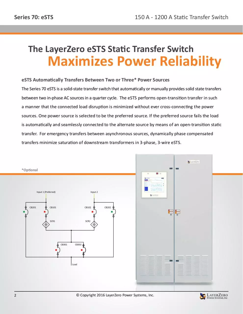
eSTS Automatically Transfers Between Two or Three* Power Sources
The Series 70 eSTS is a solid-state transfer switch that automatically or manually provides solid state transfers
between two in-phase AC sources in a quarter cycle. The eSTS performs open-transition transfer in such
a manner that the connected load disruption is minimized without ever cross-connecting the power
sources. One power source is selected to be the preferred source. If the preferred source fails the load
is automatically and seamlessly connected to the alternate source by means of an open-transition static
transfer. For emergency transfers between asynchronous sources, dynamically phase compensated
transfers minimize saturation of downstream transformers in 3-phase, 3-wire eSTS.
*Optional
2
© Copyright 2016 LayerZero Power Systems, Inc.
Series 70: eSTS
150 A - 1200 A Static Transfer Switch
Equipment Layout (400 A Shown)
Controls Section Contains:
Power electronics
• SCRs (Silicon Control Rectifier) in
Convection Cooled Heat Sinks
Control Electronics
• System Control & Data Acqusition
Boards
• SCR Gate Drives
• Redundant Power Supply System
• I/O system; VPN Router
CB Section Contains:
Input isolation switches
Bypass isolation Switches
Output isolation switches
Source connection terminals
Load connection terminals
1200 A Shown
Controls Section
Power Electronics Section
Input/Output Bypass Isolation Section
Source & Load Terminal Section
3
© Copyright 2016 LayerZero Power Systems, Inc.
Series 70: eSTS
150 A - 1200 A Static Transfer Switch
Equipment Construction Detail (400 A Shown)
Source 1 Phase A SCRs
Source 2 Phase A SCRs
CB101 Source 1 Isolate
CB102 Source 2 Isolate
CB201 Bypass Isolate,
Source 1
CB202 Bypass Isolate,
Source 2
Source 2 Phase B SCRs
Source 1 Phase B SCRs
CB301 Output Isolate 1
CB302 Output Isolate 2,
(Redundant, Optional)
Source 1 Phase C SCRs
Source 2 Phase C SCRs
2
1
15” Color Touch Screen (Standard)
3
1. Stereo Speakers for Guided Bypass Prompts
2. Output On Light (Remains Lit in Bypass Isolate Mode)
3. Alarm & Bypass Indicator
4
5
6
4. SCB Status Indicator
5. Logged In User
6. Navigation Menu
20
7
7. Customer & Project Information
8. Date & Time
4
© Copyright 2016 LayerZero Power Systems, Inc.
8
Series 70: eSTS
150 A - 1200 A Static Transfer Switch
Equipment Construction Detail (800 A Shown)
1
1. Alarmed Doors
2
2. Hinged Dead Front Doors
3
3. Silver Plated Terminals
4. 15” Color Touch Screen GUI
4
6
5. Printed Bypass Instructions
7
8
5
6. Polycarbonate Window
7. InSight™ IR Portholes
9
8. Convection Cooled Heat Sinks
9. Staggered Gate Drive Arrangement
10. Epoxy Coated Buswork
10
11
11. Circuit Breakers
12. Redundant Power Supplies
13. Convection Cooled Intake
12
13
1200 A Shown
1
1. Alarmed Doors
2
2. Hinged Dead Front Doors
3. 15” Color Touch Screen GUI
4. Printed Bypass Instructions
4
3
8
5. InSight™ IR Portholes
5
7
6. Convection Cooled Heat Sinks
6
9
7. Staggered Gate Drive Arrangement
8. Epoxy Coated Buswork
9. Circuit Breakers
10
10. Redundant Power Supplies
11. Convection Cooled Intake
5
11
© Copyright 2016 LayerZero Power Systems, Inc.
Series 70: eSTS
150 A - 1200 A Static Transfer Switch
Features/Power Quality Monitoring
Reliability
Current Metering Point
V
Voltage Metering Point
PQ
Power Quality Metering Point
BM
Branch Current Monitoring
Safety
Safe Bypass Procedure
InSight™ IR Portholes
Waveform Capture
Voice Guided Bypass
Sectionalized Components
“Black Box” Forensic Diagnostics
Optional Triple Modular Redundancy
Polycarbonate Windows
Touch Screen Interface
Epoxy Coated Buswork
Front-Only Access
Waveforms Automatically Emailed
Silver Plated Terminals
Dead-Front Hinged Doors
Maintenance-Free Joints
Connectivity
Machined Hardware
6
A
Screw Thread Inserts
Ethernet Connectivity
Convection Cooling
Modbus/TCP
Optical Fiber Based Controls
NTP Time Clock Synchronization
Serialized Critical Board Tracking
SNMP Connectivity
© Copyright 2016 LayerZero Power Systems, Inc.
Series 70: eSTS
150 A - 1200 A Static Transfer Switch
Zen SSQM Technical Specifications
Zen SSQM Parameters
Mains
Voltage (Volts)
Voltage Average of Phases (Volts)
Voltage Inputs and Output
Frequency (Hertz)
Total Harmonic Distortion (Percent VTHD)
Phase Rotation
Current (Amps)
Current Average of Phases (Amps)
Current Imbalance (Percent)
Real Power (kilowatts)
Apparent Power (kilovolt-amperes)
Current Inputs
Reactive Power (kilovolt-amperes reactive)
Power Factor
Crest Factor
Crest Factor Average of Phases
Phase Difference Between Sources
Phase Difference Between Sources and Output
Summary Alarm
On Source (1/2/3)
Source Fail (1/2/3)
Source Preferred (1/2/3)
Source 1st Alternate (1/2/3)
Source Over/Under Voltage (1/2/3)
Alarms
Source Over/Under Frequency (1/2/3)
Source Not Available (1/2/3)
Output Failure
Source Overcurrent (1/2/3)
Source Exceeds Manual Limit (1/2/3)
Source Exceeds Automatic Limit (1/2/3)
Bypassed to Source (1/2/3)
7
© Copyright 2016 LayerZero Power Systems, Inc.
Series 70: eSTS
150 A - 1200 A Static Transfer Switch
Reliability Overview
LayerZero eSTS Reliability Overview
The LayerZero eSTS Provides Many Dimensions of Reliability:
• Control System Reliability
• SMR (Single Module Redundancy, Standard)
• TMR (Triple Modular Redundancy, Optional)
• Control Power Supply Reliability
• Signal Reliability
• Operator Procedural Reliability
Single Module Redundancy (SMR) Reliability (Standard)
Fiber Optics
Single Module Redundancy is a cost-effective topology
Gate Drive 1
Source 1 A
that provides redundant power paths to mission-critical
equipment. In SMR systems, sources each have built-in
Gate Drive 2
Source 1 B
triple redundancy of processors.
Gate Drive 3
Source 1 C
Source 1
Control
In addition, every phase is controlled with a separate
Source 2
Control
gate drive board.
SCB 1
Gate Drive 4
Source 2 A
WAN Port
LayerZero Single Modular Redundant topology is unique
that it the system is fail-safe, maintaining full switching
functionality even if a critical board were to fail.
8
© Copyright 2016 LayerZero Power Systems, Inc.
Gate Drive 5
Source 2 B
Gate Drive 6
Source 2 C
Series 70: eSTS
150 A - 1200 A Static Transfer Switch
Reliability Features: Triple Modular Redundancy (TMR) *Optional
Triple Modular Redundancy (TMR) Reliability (Optional)
LayerZero TMR has all the redundancy of SMR, plus each
STS has three independent sets of analog and digital
data acquisition and control systems. There is no direct
communication between the three systems. The three
systems do not even share a common system clock.
• Each control system acquires voltage and current data
independently
• Each control system determines whether a source is
good/bad independently
• Upon loss of a source, each control system makes
decisions to transfer independently
Even if an entire control path or its subcomponent were to
fail; and then if the active power source were to fail, the
STS is able to complete its mission of transferring to the
alternate source.
Fiber Optics
Source 1
Control
Gate Drive 1
Source 1 A
Source 2
Control
SCB 1
Gate Drive 2
Source 1 B
Gate Drive 3
Source 1 C
Source 1
Control
Source 2
Control
SCB 2
(TMR)
Gate Drive 4
Source 2 A
WAN Port
Gate Drive 5
Source 2 B
Source 1
Control
Source 2
Control
SCB 3
(TMR)
9
© Copyright 2016 LayerZero Power Systems, Inc.
Gate Drive 6
Source 2 C
Download LayerZero Series 70 eSTS
LayerZero Series 70 eSTS.pdf (PDF, 5.26 MB)
Download PDF
Share this file on social networks
Link to this page
Permanent link
Use the permanent link to the download page to share your document on Facebook, Twitter, LinkedIn, or directly with a contact by e-Mail, Messenger, Whatsapp, Line..
Short link
Use the short link to share your document on Twitter or by text message (SMS)
HTML Code
Copy the following HTML code to share your document on a Website or Blog
QR Code to this page

This file has been shared publicly by a user of PDF Archive.
Document ID: 0000360347.