TurnCounterHowto (PDF)
File information
This PDF 1.5 document has been generated by / Skia/PDF m52, and has been sent on pdf-archive.com on 25/05/2016 at 10:06, from IP address 98.155.x.x.
The current document download page has been viewed 296 times.
File size: 115.29 KB (4 pages).
Privacy: public file


File preview
Setting up the turn counter
Analog triggers
Analog triggers convert analog signals into digital signals using the cRIO’s FPGA. In order to
make the turn counter work, we use an analog trigger to create a digital signal when the
potentiometer “wraps around” from 0° to 360° or 360° to 0°.
Code sample (creating an analog trigger):
AnalogTrigger
_analogTrigger
=
new
AnalogTrigger
(
channel
);
Analog trigger outputs
The analog trigger can send outputs in a number of different modes. The two most useful to us
here are Rising Pulse and Falling Pulse. Rising Pulse sends a pulse of digital signal when the
analog signal changes from a value below the minimum voltage you’ve set (hereafter called the
“lower threshold”) to a value above the maximum voltage you’ve set (the “upper threshold”).
Falling Pulse sends a pulse when the signal changes from a value above the upper threshold to
one below the lower threshold. One of these should pulse whenever you hit the potentiometer’s
discontinuity; which one indicates the direction the wheel pod is turning.
Code sample (creating analog trigger outputs):
AnalogTriggerOutput
_analogTriggerFalling
=
new
AnalogTriggerOutput
(
_analogTrigger
,
AnalogTriggerOutput
.
Type
.
kFallingPulse
);
AnalogTriggerOutput
_analogTriggerRising
=
new
AnalogTriggerOutput
(
_analogTrigger
,
AnalogTriggerOutput
.
Type
.
kRisingPulse
);
Creating the counter
To create a turn counter, we need to count the digital pulses of the analog trigger outputs. When
one pulses, we should increment the counter; when the other pulses, we should decrement it.
Which is which depends on your setup.
Code sample (creating the turn counter):
Counter
_turnCounter
=
new
Counter
();
_turnCounter
.
setUpDownCounterMode
();
_turnCounter
.
setUpSource
(
_analogTriggerRising
);
_turnCounter
.
setDownSource
(
_analogTriggerFalling
);
_turnCounter
.
start
();
The filter, setting the sample rate and threshold voltages
Although the potentiometer’s discontinuity normally looks like a straight vertical line of voltage, it
isn’t; it’s a very steep, notquitevertical line. Thus, when crossing it, there’s a chance that one of
the voltages sampled by the analog trigger will be on that line, which really messes things up.
Luckily, you can enable a filter on the analog trigger’s input that samples three points and
rejects the one closest to average. In this way, so long as no more than one sampled point in a
row lies on the discontinuity and the surrounding points are below / above the lower / upper
threshold voltages, the crossing will still be detected. We need to set the sample rate low
enough that no more than one point can lie on the line.
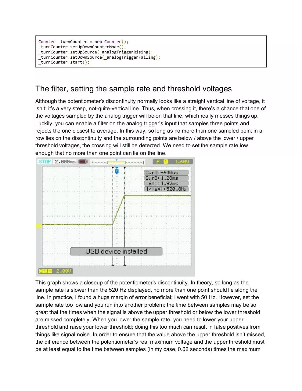
This graph shows a closeup of the potentiometer’s discontinuity. In theory, so long as the
sample rate is slower than the 520 Hz displayed, no more than one point should lie along the
line. In practice, I found a huge margin of error beneficial; I went with 50 Hz. However, set the
sample rate too low and you run into another problem: the time between samples may be so
great that the times when the signal is above the upper threshold or below the lower threshold
are missed completely. When you lower the sample rate, you need to lower your upper
threshold and raise your lower threshold; doing this too much can result in false positives from
things like signal noise. In order to ensure that the value above the upper threshold isn’t missed,
the difference between the potentiometer’s real maximum voltage and the upper threshold must
be at least equal to the time between samples (in my case, 0.02 seconds) times the maximum
rate of change of the voltage. The same must be true of the difference between the
potentiometer’s real minimum voltage and the lower threshold. I wound up using a
“realthreshold” voltage difference of 0.6V. To get false positives, the two thresholds have to be
pretty close; once again, big safety margins are your friend.
Code sample (enabling input filtering):
_analogTrigger
.
setFiltered
(
true
);
Code sample (setting the thresholds):
double
_sensingVoltageDifference
=
0.6;
_analogTrigger
.
setLimitsVoltage
(
minVoltage
+
_sensingVoltageDifference
,
maxVoltage
_sensingVoltageDifference
);
Code sample (setting the sample rate):
int
DEFAULT_ANALOG_MODULE
=
1;
int
ANALOG_SAMPLE_RATE
=
50
;
//Hz
AnalogModule
module
=
(
AnalogModule
)
Module
.
getModule
(
ModulePresence
.
ModuleType
.
kAnalog
,
DEFAULT_ANALOG_MODULE
);
module
.
setSampleRate
(
ANALOG_SAMPLE_RATE
);
Computing the new degree measurement
The end goal of this is to create a potentiometer that reads beyond 360°. To get this reading,
simply multiply the turn count by 360° and add the wheel’s current heading.
Code sample (reading the new degree measurement):
double
heading
=
(((
voltage
_minVoltage
)
*
(
360.0
/
_maxVoltage
)))
%
360.0;
double
degrees
=
heading
+
(
_turnCounter
.
get
()
*
360.0
);
Putting it all together
Here’s my final code. I don’t know if things need to be in this order (as opposed to the order
presented above) but it certainly works for me.
// Constants //
private
static
final
int
ANALOG_SAMPLE_RATE
=
50;
private
static
final
int
DEFAULT_ANALOG_MODULE
=
1
;
private
static
final
double
_sensingVoltageDifference
=
0.6;
// Global fields //
private
AnalogTrigger
_analogTrigger;
private
Counter
_turnCounter;
private
AnalogTriggerOutput
_analogTriggerFalling;
private
AnalogTriggerOutput
_analogTriggerRising;
// In potentiometer's constructor //
_analogTrigger
=
new
AnalogTrigger
(
channel
);
_analogTrigger
.
setFiltered
(
true
);
_analogTrigger
.
setLimitsVoltage
(
minVoltage
+
_sensingVoltageDifference
,
maxVoltage
_sensingVoltageDifference
);
_analogTriggerFalling
=
new
AnalogTriggerOutput
(
_analogTrigger
,
AnalogTriggerOutput
.
Type
.
kFallingPulse
);
_analogTriggerRising
=
new
AnalogTriggerOutput
(
_analogTrigger
,
AnalogTriggerOutput
.
Type
.
kRisingPulse
);
AnalogModule
module
=
(
AnalogModule
)
Module
.
getModule
(
ModulePresence
.
ModuleType
.
kAnalog
,
DEFAULT_ANALOG_MODULE
);
module
.
setSampleRate
(
ANALOG_SAMPLE_RATE
);
_turnCounter
=
new
Counter
();
_turnCounter
.
setUpDownCounterMode
();
_turnCounter
.
setUpSource
(
_analogTriggerRising
);
_turnCounter
.
setDownSource
(
_analogTriggerFalling
);
_turnCounter
.
start
();
// getDegrees() function //
double
heading
=
(((
voltage
_minVoltage
)
*
(
360.0
/
_maxVoltage
)))
%
360.0;
double
degrees
=
heading
+
_offsetDegrees
+
(
_turnCounter
.
get
()
*
360.0
);
//I have an
"offset" that allows me to compensate for potentiometers that aren't installed exactly
straight
Download TurnCounterHowto
TurnCounterHowto.pdf (PDF, 115.29 KB)
Download PDF
Share this file on social networks
Link to this page
Permanent link
Use the permanent link to the download page to share your document on Facebook, Twitter, LinkedIn, or directly with a contact by e-Mail, Messenger, Whatsapp, Line..
Short link
Use the short link to share your document on Twitter or by text message (SMS)
HTML Code
Copy the following HTML code to share your document on a Website or Blog
QR Code to this page

This file has been shared publicly by a user of PDF Archive.
Document ID: 0000376571.