SAIO GUIDE V1.0 (PDF)
File information
Author: Giles Burgess
This PDF 1.5 document has been generated by Microsoft® Word 2013, and has been sent on pdf-archive.com on 08/01/2017 at 17:21, from IP address 82.37.x.x.
The current document download page has been viewed 6067 times.
File size: 9.64 MB (83 pages).
Privacy: public file


File preview
KITE’S SUPER AIO CONSTRUCTION GUIDE
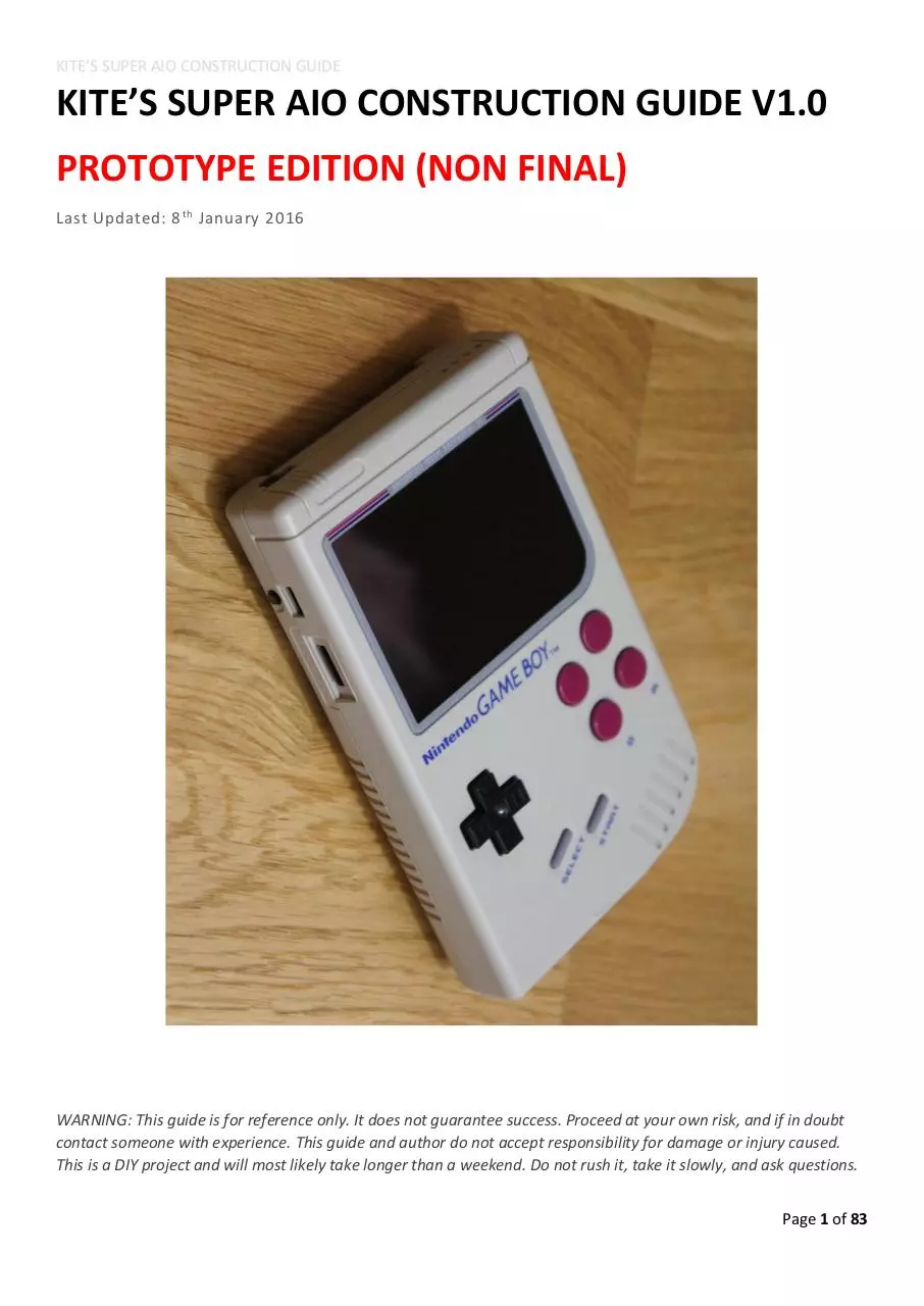
KITE’S SUPER AIO CONSTRUCTION GUIDE V1.0
PROTOTYPE EDITION (NON FINAL)
Last Updated: 8 th January 2016
WARNING: This guide is for reference only. It does not guarantee success. Proceed at your own risk, and if in doubt
contact someone with experience. This guide and author do not accept responsibility for damage or injury caused.
This is a DIY project and will most likely take longer than a weekend. Do not rush it, take it slowly, and ask questions.
Page 1 of 83
KITE’S SUPER AIO CONSTRUCTION GUIDE
Table of Contents
1 INTRODUCTION .............................................................................................................................................................. 6
1.1 Foreword ................................................................................................................................................................. 6
1.2 Overview ................................................................................................................................................................. 6
1.3 Parts Required......................................................................................................................................................... 6
1.4 Tools Required ........................................................................................................................................................ 6
1.5 Skills Required ......................................................................................................................................................... 7
1.6 Build Steps Overview .............................................................................................................................................. 7
2 Super AIO Hardware Overview ...................................................................................................................................... 9
2.1 TOP .......................................................................................................................................................................... 9
2.2 BOTTOM ................................................................................................................................................................ 10
2.3 OUTLINE ................................................................................................................................................................ 11
3 Phase 1 – Prepare and Test Boards.............................................................................................................................. 12
3.1 Solder Mode Button and Switch to 4pin Cable. .................................................................................................... 12
3.1.1 Prepare and Solder the Slide Switch .............................................................................................................. 12
3.1.2 Prepare and Solder the Button ...................................................................................................................... 13
3.1.3 Examine Finished Cable ................................................................................................................................. 13
3.2 Prepare Back Board Spacer ................................................................................................................................... 14
3.2.1 Break Out Tabs and Prepare Spacer 1 ........................................................................................................... 14
3.2.2 Prepare Spacer 2 ............................................................................................................................................ 15
3.2.3 Test for Fit ...................................................................................................................................................... 15
3.3 Solder USB Port to Back Board.............................................................................................................................. 15
3.3.1 Determine ‘correct’ way up for USB Port ...................................................................................................... 16
3.3.2 Bend USB Port Legs to meet PCB ................................................................................................................... 16
3.3.3 Test Fit to Work Out Placement ..................................................................................................................... 16
3.3.4 Solder All Connectors ..................................................................................................................................... 17
3.3.5 Final Test Fit ................................................................................................................................................... 17
3.3.6 Test Main Board before Soldering ................................................................................................................. 17
3.4 Prepare Raspberry Pi Zero .................................................................................................................................... 18
3.4.1 Cut the Pi ........................................................................................................................................................ 18
3.4.2 Test Pi Zero..................................................................................................................................................... 18
3.5 Solder Pi Zero to Main Board ................................................................................................................................ 19
3.5.1 Preparing the USB Pads.................................................................................................................................. 19
3.5.2 Prepare SD Pads ............................................................................................................................................. 21
3.5.3 Prepare Main Board Pads .............................................................................................................................. 21
3.5.4 Align USB, SD, and Power GPIO Pads of Pi ..................................................................................................... 21
Page 2 of 83
KITE’S SUPER AIO CONSTRUCTION GUIDE
3.5.5 Solder USB and SD Pads of Pi ......................................................................................................................... 22
3.5.6 Solder Power GPIO Pads of Pi ........................................................................................................................ 24
3.6 Test Pi booting/Buttons/Audio/WiFi/etc. ............................................................................................................. 25
3.6.1 Preparation for Initial Testing ........................................................................................................................ 25
3.6.2 Setup for Initial Testing .................................................................................................................................. 26
3.6.3 Troubleshooting First Default Boot................................................................................................................ 28
3.6.3.1 No Board Power ...................................................................................................................................... 29
3.6.3.2 Pi does not boot ...................................................................................................................................... 29
3.6.3.3 Gamepad not detected ........................................................................................................................... 29
3.6.3.4 External USB not working ....................................................................................................................... 29
3.7 Solder Status LEDs ................................................................................................................................................. 30
3.8 Solder Remaining GPIO Pins.................................................................................................................................. 32
3.8.1 Solder the Connectors.................................................................................................................................... 32
3.8.2 Test the LCD ................................................................................................................................................... 33
3.8.3 LCD Troubleshooting ...................................................................................................................................... 33
4 Phase 2 – Prepare front half of case ............................................................................................................................ 34
4.1 Drill Button Holes .................................................................................................................................................. 34
4.1.1 Prepare Drill Holes ......................................................................................................................................... 34
4.1.2 Drill Pilot Hole ................................................................................................................................................ 35
4.1.3 Enlarge Hole ................................................................................................................................................... 36
4.1.4 Sand and Deburr ............................................................................................................................................ 36
4.1.5 Make the Second Hole ................................................................................................................................... 37
4.2 Cut Out Screen Area.............................................................................................................................................. 37
4.2.1 Cut Posts as Low as Possible .......................................................................................................................... 38
4.2.2 Cut out Approx. Screen Area.......................................................................................................................... 38
4.2.3 Use Knife to Trim and Neaten up Screen Area .............................................................................................. 39
4.3 Glue Button Wells ................................................................................................................................................. 41
4.3.1 Prepare Wells ................................................................................................................................................. 41
4.3.2 Glue Wells ...................................................................................................................................................... 41
4.3.3 Make adjustments ......................................................................................................................................... 43
4.4 Drill LED Holes and Fill with Glue .......................................................................................................................... 45
4.4.1 Prepare LED Holes .......................................................................................................................................... 45
4.4.2 Drill LED Holes ................................................................................................................................................ 45
4.4.3 Fill LED Holes with Hot Glue ........................................................................................................................... 47
4.4.4 Clean up LED Holes......................................................................................................................................... 48
4.5 Cut USB Port Hole ................................................................................................................................................. 49
4.5.1 Prepare USB Port Hole ................................................................................................................................... 49
Page 3 of 83
KITE’S SUPER AIO CONSTRUCTION GUIDE
4.5.2 Cut USB Port Hole .......................................................................................................................................... 49
4.5.3 Trim and Adjust USB Port Hole ...................................................................................................................... 50
4.6 Fit Speaker............................................................................................................................................................. 52
4.7 Fit LCD ................................................................................................................................................................... 53
4.7.1 Place LCD ........................................................................................................................................................ 53
4.7.2 Tack Screen in Place (don’t glue too much just yet!) ..................................................................................... 55
4.7.3 Preview and test ............................................................................................................................................ 55
5 Phase 3 – Test Electronics inside Case ......................................................................................................................... 56
5.1 Test Fit Main Board in to Front Half of Case ......................................................................................................... 56
6 Phase 4 – Prepare Back Half of Case ............................................................................................................................ 57
6.1 Tools for the Job.................................................................................................................................................... 57
6.2 Cut Out Battery Bay .............................................................................................................................................. 57
6.3 Cut Out L and R Button Holes ............................................................................................................................... 59
6.4 Fit Power Switch and Mode Button ...................................................................................................................... 62
6.4.1 Fit Power Switch............................................................................................................................................. 62
6.4.2 Fit Mode Button ............................................................................................................................................. 65
6.4.3 Test Switch and Button .................................................................................................................................. 65
6.5 Fit Back Board ....................................................................................................................................................... 66
6.6 Test Fitment of Front Half of Case ........................................................................................................................ 67
7 Phase 5 – Finish Front Half of Case .............................................................................................................................. 68
7.1 Glue Mounting Posts ............................................................................................................................................. 68
7.1.1 Prepare Mounting Locations.......................................................................................................................... 68
7.1.2 Prepare Mounting Posts ................................................................................................................................ 70
7.1.3 Tack Mounting Posts ...................................................................................................................................... 71
7.1.4 Glue Mounting Post ....................................................................................................................................... 72
7.1.4.1 Initial Glue ............................................................................................................................................... 72
7.1.4.2 Initial Fitment .......................................................................................................................................... 74
7.1.4.3 Tidy-up .................................................................................................................................................... 74
7.1.4.4 Final Fitment ........................................................................................................................................... 74
7.1.5 Attempt to Close Entire Case to Check for Fitment ....................................................................................... 75
7.1.6 Repeat for all Posts ........................................................................................................................................ 75
7.2 Check for Fitment Again ........................................................................................................................................ 75
7.3 Glue Screen Fully ................................................................................................................................................... 75
8 Phase 6 –Prepare Battery Bay Door (optional): ........................................................................................................... 76
8.1 Glue Magnets ........................................................................................................................................................ 76
9 Phase 7 – Finalise ......................................................................................................................................................... 77
9.1 Test Fit Battery Placement and Blank Cartridge ................................................................................................... 77
Page 4 of 83
KITE’S SUPER AIO CONSTRUCTION GUIDE
9.2 Plan Wire Placement ............................................................................................................................................. 78
9.3 Install Buttons and Membranes ............................................................................................................................ 79
9.4 Test All Functionality ............................................................................................................................................. 80
9.5 Affix Screen Surround ........................................................................................................................................... 80
9.6 Screw Case Closed................................................................................................................................................. 81
9.7 Finished Project..................................................................................................................................................... 82
10 Installing SUPER AIO Software on to RetroPie ........................................................................................................... 83
Page 5 of 83
KITE’S SUPER AIO CONSTRUCTION GUIDE
1 INTRODUCTION
1.1 Foreword
Massive thanks for trying out my Super AIO board I hope you enjoy the project!
This guide contains images for the PROTOTYPE version of the board, not the final shipping one. There are VERY
minor changes between them and this guide will be updated to reflect the shipping version. The main difference is
that backboard is a slightly different shape and the external USB cable plugs in to a different place (the top side of
the board, rather than the back (which was really awkward).
1.2 Overview
This guide will help you in building your own gaming system using a SUPER AIO board! This guide is technically more
of a build log, however it will point out a number of hints and tips to make your build go smoothly!
The guide will be broken down into a number of sections. It is important that you read through everything before
undertaking any work, because it is always good to know what the next step is to hopefully prevent modifications
that later on aren’t compatible (e.g. “I don’t need this part, I’ll just throw it away” … followed by a step requiring said
part!). It’s your project, make all the decisions yourself. Use this guide as inspiration and for tips.
1.3 Parts Required
The following list details all the parts used in this guide:
Kite’s SUPER AIO board.
o This includes the LCD, back board, cables, USB port, tactile button, power switch, LEDs.
Plastic console case including screws and power switch plastic.
Additional X Y buttons for case.
Additional button membranes for case (the rubber bits).
Button wells.
o 3D printed or from SNES controller.
Back buttons.
2000-3000mAh LiPo battery.
30/32mm speaker 4 or 8 ohm (thinner the better).
Pi Zero.
Micro SD card (8GB or larger).
Screen surround.
Micro magnets (3x1mm).
M2 Bolt (~20mm) + Nuts (2x).
1.4 Tools Required
The following list details all the tools used in this guide:
Adjustable temperature soldering iron.
Quality solder.
o 63/37 with flux.
Flux pen.
Rotary cutting tool with cutting disk.
Hot glue gun.
Scalpel.
Page 6 of 83
KITE’S SUPER AIO CONSTRUCTION GUIDE
Utility knife (e.g. Stanley knife).
Needle nosed tweezers.
Needle nosed pliers + flat pliers.
Sandpaper.
Assorted small files.
Small magnetic screwdriver.
Step drill bit (3-12mm). MUST contain an ‘11mm’ layer.
Kapton tape.
1.5 Skills Required
The following skills will prove very useful for completing this project, so either practice them yourself (e.g. soldering
on a breadboard to gain soldering practice) or make friends with the right people!
Soldering
o The key to success is an adjustable temp iron and good solder. From experience any solder from a
generic hardware shop will lead to disappointment. See tools list above for recommendations. There
isn’t too much soldering required here, but it can be tricky. USE HIGH QUALITY SOLDER NOT FROM A
SHOP!! Solder makes all the difference. Use an adjustable temp iron. 250-270 degrees C is my ideal,
do not go any higher.
Cutting and carving
o The plastic cases are very soft, and using a sharp knife to ‘carve’ or ‘plane’ the plastic smooth or to
shape makes for a much better finish (a rotary cutting tool will melt everything, but is useful for
removing big chunks, and files/sanding will leave a rough finish).
o You need to be VERY careful if you are new to this, blades are sharp and if used with force they can
slip and really hurt you.
Gluing
o Handling hot glue is an art, in this guide we will glue on the mounting posts. Getting a solid hold is
key to keeping everything together! Tips are given during this step in the guide.
1.6 Build Steps Overview
The following steps are a generalised overview on the steps required and their approximate order. You can do them
in whatever order you like but it is key to stress on testing often, especially with the electronic components! You
don’t want to have it all closed up and then it not turn on.. so test test test!
1. Test electronics:
a. Solder mode button and switch to 4pin cable.
b. Solder USB port to back board.
c. Solder Pi Zero to main board.
d. Test Pi booting/Buttons/Audio/WiFi/etc.
e. Solder LEDs.
2. Prepare front half of case:
a. Drill button holes.
b. Glue button wells.
c. Drill LED holes and fill with glue.
d. Cut USB port hole.
e. Fit speaker.
f. Cut LCD hole.
i. Cut posts as low as possible.
ii. Cut out approx. screen area.
iii. Use knife to trim and neaten up screen area.
Page 7 of 83
KITE’S SUPER AIO CONSTRUCTION GUIDE
g. Fit LCD:
i. Tack screen in place (don’t glue too much just yet!).
3. Test electronics:
a. Test fit main board in to front half of case.
b. Test all electronics again.
4. Finish front half of case:
a. Glue mounting posts.
i. Check for fitment on EVERY post, one by one.
b. Glue screen firmly.
5. Prepare back half of case:
a. Cut out battery bay.
b. Cut out L and R button holes.
c. Fit power switch.
d. Fit mode button.
e. Fit back board.
f. Test fitment of front half of case.
6. Prepare battery bay door (optional):
a. Cut tab.
b. Glue magnets.
7. Finalise:
a. Test fit battery placement.
b. Plan wire placement.
c. Slowly close case.
d. Test all functionality.
e. Stick screen border.
f. Screw case closed.
The table of contents at the start of this document contains more detail on the actual order of steps. The above list
has been simplified.
Page 8 of 83
KITE’S SUPER AIO CONSTRUCTION GUIDE
2 Super AIO Hardware Overview
2.1 TOP
Page 9 of 83
Download SAIO GUIDE V1.0
SAIO_GUIDE_V1.0.pdf (PDF, 9.64 MB)
Download PDF
Share this file on social networks
Link to this page
Permanent link
Use the permanent link to the download page to share your document on Facebook, Twitter, LinkedIn, or directly with a contact by e-Mail, Messenger, Whatsapp, Line..
Short link
Use the short link to share your document on Twitter or by text message (SMS)
HTML Code
Copy the following HTML code to share your document on a Website or Blog
QR Code to this page

This file has been shared publicly by a user of PDF Archive.
Document ID: 0000533378.