Jammers4u CT 6067 UAV Drone Jammer User manual V.16.12 (PDF)
File information
Title: Jammers4u
Author: Toshiba
This PDF 1.5 document has been generated by Microsoft® Word 2010, and has been sent on pdf-archive.com on 05/03/2017 at 09:44, from IP address 85.203.x.x.
The current document download page has been viewed 514 times.
File size: 882.32 KB (6 pages).
Privacy: public file


File preview
CT-6067 Series
Pelican jamming system
User manual
1
Foreword
This manual is the operating instructions of the CT-6067 Series Jammer (referred to as the
“unit” in this manual).
The unit outputs 15-100W for each of the 6 bands 1570-1620MHz,
2400-2500MHz, 433MHz, 5700-5900MHz, 865-920MHz, 1220-1260MHz
Safety guidelines
Read the following guidelines before using the unit.
guidelines may be dangerous or illegal.
Failure to comply with these
In any event of doubt, consult your local
distributor or Vendor’s support staff before use.
Handling and transportation
Take maximum care while handling the unit.
Environmental conditions
Do not place the unit near heat sources.
The unit dissipates a lot of heat.
block its ventilation holes and do not insert any objects through them.
Never
Always
allow at least 10 cm clearance in front of ventilation holes on two sides for free air
circulation
Qualified service
Only trained service personnel qualified by Vendor are allowed to diagnose and maintain
the unit in accordance with established safety practices and standards.
Features
Jamming frequency
CH1: 1570MHz-1620MHz 100W
CH2: 24000MHz-2500MHz 100W
CH3: 433MHz 100W
CH4: 5700MHz – 5900MHz 15W
CH5: 860MHz – 920MHz:100W
CH6: 1220MHz – 1260MHz :100W
The unit has output power for 100W for each of Five bands and 5.8GHz is 15W
Omni antennas (3-8dBi).
2
The Conditions in the system are indicated by the LEDs.
The input power applied from 110V or 220V AC.
General Description
6 Omni
Antnnas
Power
Adapter
Main Power Switch
Antenna’s Cable
AC Power Adaper
External Battery
Power Switch
All Dins Down…Max
Output Power
AC 110-240V
Power
Cable
3
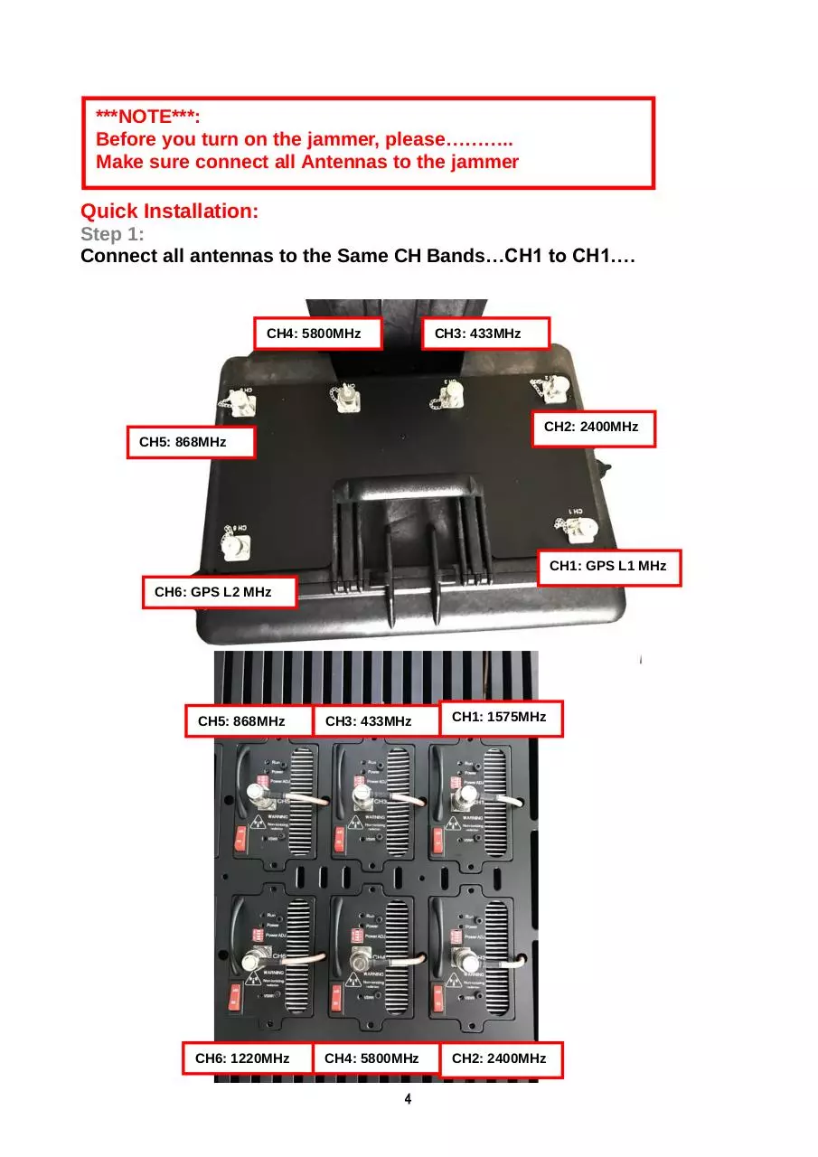
***NOTE***:
Before you turn on the jammer, please………..
Make sure connect all Antennas to the jammer
Quick Installation:
Step 1:
Connect all antennas to the Same CH Bands…CH1 to CH1….
CH4: 5800MHz
CH3: 433MHz
CH2: 2400MHz
CH5: 868MHz
CH1: GPS L1 MHz
CH6: GPS L2 MHz
CH5: 868MHz
CH3: 433MHz
CH1: 1575MHz
CH6: 1220MHz
CH4: 5800MHz
CH2: 2400MHz
4
Step 2:
Turn “ Main Power” ON
Step 2:
Switch ON
on Main Power after you
connect all Antennas to
the Jammer
Step 3:
Turn Each Band “ ON “…….
Step 3:
Switch ON Each Band
Step 4:
Turn Each Band Output Power to MAX… ALL Dins DOWN to MAX.
Power Switch
All Dins Down…Max
Output Power
5
External Battery Options: B-50AH
AC 220V Power
Cord for Charging
Connect to Jammer
Main Siwtch
Battery LED Status
Battery AH Percent
Left
Battery AH Left
Estimated Working
Time Left
Current Battery Vlotage
The Jammer work
Current Amp
6
Download Jammers4u CT-6067-UAV Drone Jammer User manual V.16.12
Jammers4u CT-6067-UAV Drone Jammer User manual V.16.12.pdf (PDF, 882.32 KB)
Download PDF
Share this file on social networks
Link to this page
Permanent link
Use the permanent link to the download page to share your document on Facebook, Twitter, LinkedIn, or directly with a contact by e-Mail, Messenger, Whatsapp, Line..
Short link
Use the short link to share your document on Twitter or by text message (SMS)
HTML Code
Copy the following HTML code to share your document on a Website or Blog
QR Code to this page

This file has been shared publicly by a user of PDF Archive.
Document ID: 0000563988.