chapter 25 (PDF)
File information
Title: Fundamental of Physics
Author: Halliday/Resnick
This PDF 1.5 document has been generated by Microsoft® Word 2010, and has been sent on pdf-archive.com on 31/05/2017 at 01:51, from IP address 177.158.x.x.
The current document download page has been viewed 1872 times.
File size: 494.19 KB (32 pages).
Privacy: public file


File preview
Chapter 25
1. (a) The capacitance of the system is
C
q
70 pC
35
. pF.
V
20 V
(b) The capacitance is independent of q; it is still 3.5 pF.
(c) The potential difference becomes
V
q 200 pC
57 V.
C 35
. pF
2. Charge flows until the potential difference across the capacitor is the same as the
potential difference across the battery. The charge on the capacitor is then q = CV, and
this is the same as the total charge that has passed through the battery. Thus,
q = (25 10–6 F)(120 V) = 3.0 10–3 C.
3. THINK The capacitance of a parallel-plate capacitor is given by C = 0A/d, where A is
the area of each plate and d is the plate separation.
EXPRESS Since the plates are circular, the plate area is A = R2, where R is the radius
of a plate. The charge on the positive plate is given by q = CV, where V is the potential
difference across the plates.
ANALYZE (a) Substituting the values given, the capacitance is
C
0 R 2
d
8.8510
12
F m 8.2 102 m
2
3
1.310 m
1.44 1010 F 144 pF.
(b) Similarly, the charge on the plate when V = 120 V is
q = (1.44 10–10 F)(120 V) = 1.73 10–8 C = 17.3 nC.
LEARN Capacitance depends only on geometric factors, namely, the plate area and plate
separation.
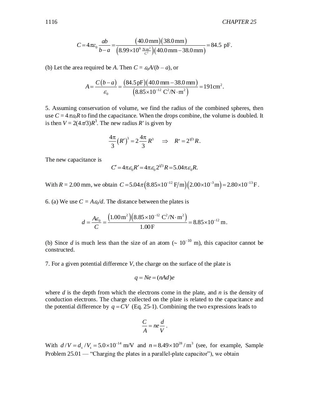
4. (a) We use Eq. 25-17:
1115
1116
CHAPTER 25
C 4 0
40.0 mm 38.0 mm
ab
84.5 pF.
b a 8.99 109 Nm2 2 40.0 mm 38.0 mm
C
(b) Let the area required be A. Then C = 0A/(b – a), or
A
C b a
0
84.5pF 40.0 mm 38.0 mm 191cm2 .
8.85 10
12
C2 /N m2
5. Assuming conservation of volume, we find the radius of the combined spheres, then
use C = 40R to find the capacitance. When the drops combine, the volume is doubled. It
is then V = 2(4/3)R3. The new radius R' is given by
4p
4p
3
R 2 R3
3
3
R 21 3 R .
The new capacitance is
C 4p 0 R 4p 0 21 3 R 5.04p 0 R.
With R = 2.00 mm, we obtain C 5.04 8.851012 F m 2.00 103 m 2.80 1013 F .
6. (a) We use C = A0/d. The distance between the plates is
d
A 0 1.00 m
C
2
8.85 10
12
C2 /N m2
1.00 F
8.85 1012 m.
(b) Since d is much less than the size of an atom ( 10–10 m), this capacitor cannot be
constructed.
7. For a given potential difference V, the charge on the surface of the plate is
q Ne (nAd )e
where d is the depth from which the electrons come in the plate, and n is the density of
conduction electrons. The charge collected on the plate is related to the capacitance and
the potential difference by q CV (Eq. 25-1). Combining the two expressions leads to
C
d
ne .
A
V
With d / V ds / Vs 5.0 1014 m/V and n 8.49 1028 / m3 (see, for example, Sample
Problem 25.01 — “Charging the plates in a parallel-plate capacitor”), we obtain
1117
C
(8.49 1028 / m3 )(1.6 1019 C)(5.0 10 14 m/V) 6.79 104 F/m2 .
A
8. The equivalent capacitance is given by Ceq = q/V, where q is the total charge on all the
capacitors and V is the potential difference across any one of them. For N identical
capacitors in parallel, Ceq = NC, where C is the capacitance of one of them. Thus,
NC q / V and
q
1.00C
N
9.09 103 .
6
VC 110V 1.00 10 F
9. The charge that passes through meter A is
b
gb
g
q CeqV 3CV 3 25.0 F 4200 V 0.315 C.
10. The equivalent capacitance is
Ceq C3
b
gb
g
10.0 F 5.00 F
C1C2
4.00F
7.33 F.
C1 C2
10.0 F 5.00 F
11. The equivalent capacitance is
Ceq
C1 C2 C3 10.0 F 5.00 F 4.00 F 3.16 F.
C1 C2 C3
10.0 F 5.00 F 4.00 F
12. The two 6.0 F capacitors are in parallel and are consequently equivalent to
Ceq 12 F . Thus, the total charge stored (before the squeezing) is
qtotal CeqV 12 F (10.0V) 120 C.
(a) and (b) As a result of the squeezing, one of the capacitors is now 12 F (due to the
inverse proportionality between C and d in Eq. 25-9), which represents an increase of
6.0 F and thus a charge increase of
qtotal CeqV 6.0 F (10.0V) 60 C .
13. THINK Charge remains conserved when a fully charged capacitor is connected to an
uncharged capacitor.
EXPRESS The charge initially on the charged capacitor is given by q = C1V0, where C1
= 100 pF is the capacitance and V0 = 50 V is the initial potential difference. After the
battery is disconnected and the second capacitor wired in parallel to the first, the charge
1118
CHAPTER 25
on the first capacitor is q1 = C1V, where V = 35 V is the new potential difference. Since
charge is conserved in the process, the charge on the second capacitor is q2 = q – q1,
where C2 is the capacitance of the second capacitor.
ANALYZE Substituting C1V0 for q and C1V for q1, we obtain q2 = C1(V0 – V). The
potential difference across the second capacitor is also V, so the capacitance of the second
capacitor is
q V V
50 V 35V
C2 2 0
C1
100 pF 42.86 pF 43pF.
V
V
35V
LEARN Capacitors in parallel have the same potential difference. To verify charge
conservation explicitly, we note that the initial charge on the first capacitor is
q C1V0 (100 pF)(50 V) 5000 pC. After the connection, the charges on each capacitor
are
q1 C1V (100 pF)(35 V) 3500 pC
q2 C2V (42.86 pF)(35 V) 1500 pC.
Indeed, q = q1 + q2.
14. (a) The potential difference across C1 is V1 = 10.0 V. Thus,
q1 = C1V1 = (10.0 F)(10.0 V) = 1.00 10–4 C.
(b) Let C = 10.0 F. We first consider the three-capacitor combination consisting of C2
and its two closest neighbors, each of capacitance C. The equivalent capacitance of this
combination is
CC
Ceq C 2 1.50 C.
C C2
Also, the voltage drop across this combination is
V
CV1
CV1
0.40V1 .
C Ceq C 1.50 C
Since this voltage difference is divided equally between C2 and the one connected in
series with it, the voltage difference across C2 satisfies V2 = V/2 = V1/5. Thus
10.0V
5
q2 C2V2 10.0 F
2.00 10 C.
5
15. (a) First, the equivalent capacitance of the two 4.00 F capacitors connected in series
is given by 4.00 F/2 = 2.00 F. This combination is then connected in parallel with two
other 2.00-F capacitors (one on each side), resulting in an equivalent capacitance C =
3(2.00 F) = 6.00 F. This is now seen to be in series with another combination, which
1119
consists of the two 3.0-F capacitors connected in parallel (which are themselves
equivalent to C' = 2(3.00 F) = 6.00 F). Thus, the equivalent capacitance of the circuit
is
CC 6.00 F 6.00 F
Ceq
3.00 F.
C C
6.00 F 6.00 F
(b) Let V = 20.0 V be the potential difference supplied by the battery. Then
q = CeqV = (3.00 F)(20.0 V) = 6.00 10–5 C.
(c) The potential difference across C1 is given by
V1
6.00 F 20.0V 10.0V .
CV
C C 6.00 F 6.00 F
(d) The charge carried by C1 is q1 = C1V1= (3.00 F)(10.0 V) = 3.00 10–5 C.
(e) The potential difference across C2 is given by V2 = V – V1 = 20.0 V – 10.0 V = 10.0 V.
(f) The charge carried by C2 is q2 = C2V2 = (2.00 F)(10.0 V) = 2.00 10–5 C.
(g) Since this voltage difference V2 is divided equally between C3 and the other 4.00-F
capacitors connected in series with it, the voltage difference across C3 is given by V3 =
V2/2 = 10.0 V/2 = 5.00 V.
(h) Thus, q3 = C3V3 = (4.00 F)(5.00 V) = 2.00 10–5 C.
16. We determine each capacitance from the slope of the appropriate line in the graph.
Thus, C1 = (12 C)/(2.0 V) = 6.0 F. Similarly, C2 = 4.0 F and C3 = 2.0 F. The total
equivalent capacitance is given by
C C2 C3
1
1
1
,
1
C123 C1 C2 C3 C1 (C2 C3 )
or
C123
C1 (C2 C3 ) (6.0 F)(4.0 F 2.0 F) 36
F 3.0 F .
C1 C2 C3 6.0 F 4.0 F 2.0 F 12
This implies that the charge on capacitor 1 is q1 (3.0 F)(6.0 V) = 18 C. The voltage
across capacitor 1 is therefore V1 = (18 C)/(6.0 F) = 3.0 V. From the discussion in
section 25-4, we conclude that the voltage across capacitor 2 must be 6.0 V – 3.0 V = 3.0
V. Consequently, the charge on capacitor 2 is (4.0 F)(3.0 V) = 12 C.
17. (a) and (b) The original potential difference V1 across C1 is
1120
CHAPTER 25
V1
CeqV
C1 C2
3.16 F100.0 V 21.1V.
10.0 F 5.00 F
Thus V1 = 100.0 V – 21.1 V = 78.9 V and
q1 = C1V1 = (10.0 F)(78.9 V) = 7.89 10–4 C.
18. We note that the voltage across C3 is V3 = (12 V – 2 V – 5 V) = 5 V. Thus, its charge
is q3 = C3 V3 = 4 C.
(a) Therefore, since C1, C2 and C3 are in series (so they have the same charge), then
4 C
C1 = 2 V = 2.0 F .
(b) Similarly, C2 = 4/5 = 0.80 F.
19. (a) and (b) We note that the charge on C3 is q3 = 12 C – 8.0 C = 4.0 C. Since the
charge on C4 is q4 = 8.0 C, then the voltage across it is q4/C4 = 2.0 V. Consequently, the
voltage V3 across C3 is 2.0 V C3 = q3/V3 = 2.0 F.
Now C3 and C4 are in parallel and are thus equivalent to 6 F capacitor which would then
be in series with C2 ; thus, Eq 25-20 leads to an equivalence of 2.0 F which is to be
thought of as being in series with the unknown C1 . We know that the total effective
capacitance of the circuit (in the sense of what the battery “sees” when it is hooked up) is
(12 C)/Vbattery = 4 F/3. Using Eq 25-20 again, we find
1
1
3
+ C =
2F
4F
1
C1 = 4.0 F .
20. For maximum capacitance the two groups of plates must face each other with
maximum area. In this case the whole capacitor consists of (n – 1) identical single
capacitors connected in parallel. Each capacitor has surface area A and plate separation d
so its capacitance is given by C0 = 0A/d. Thus, the total capacitance of the combination is
C n 1 C0
n 1 0 A (8 1)(8.851012 C2 /N m2 )(1.25104 m2 ) 2.28 1012 F.
d
3.40 103 m
21. THINK After the switches are closed, the potential differences across the capacitors
are the same and they are connected in parallel.
EXPRESS The potential difference from a to b is given by Vab = Q/Ceq, where Q is the
net charge on the combination and Ceq is the equivalent capacitance.
1121
ANALYZE (a) The equivalent capacitance is Ceq = C1 + C2 = 4.0 10–6 F. The total
charge on the combination is the net charge on either pair of connected plates. The initial
charge on capacitor 1 is
q1 C1V 1.0 106 F 100 V 1.0 104 C
and the initial charge on capacitor 2 is
q2 C2V 3.0 106 F 100 V 3.0 104 C.
With opposite polarities, the net charge on the combination is
Q = 3.0 10–4 C – 1.0 10–4 C = 2.0 10–4 C.
The potential difference is
Q 2.0 104 C
Vab
50 V.
Ceq 4.0 106 F
(b) The charge on capacitor 1 is now q1 C1Vab = (1.0 10–6 F)(50 V) = 5.0 10–5 C.
(c) The charge on capacitor 2 is now q2 C2Vab = (3.0 10–6 F)(50 V) = 1.5 10–4 C.
LEARN The potential difference Vab 50 V is half of the original V ( = 100 V), so the
final charges on the capacitors are also halved.
22. We do not employ energy conservation since, in reaching equilibrium, some energy is
dissipated either as heat or radio waves. Charge is conserved; therefore, if Q = C1Vbat =
100 C, and q1, q2 and q3 are the charges on C1, C2 and C3 after the switch is thrown to
the right and equilibrium is reached, then
Q = q1 + q2 + q3.
Since the parallel pair C2 and C3 are identical, it is clear that q2 = q3. They are in parallel
with C1 so that V1=V3, or
q1 q3
C1 C3
which leads to q1 = q3/2. Therefore,
Q (q3 / 2) q3 q3 5q3 / 2
which yields q3 = 2Q / 5 2(100 C) / 5 40 C and consequently q1 = q3/2 = 20 C.
1122
CHAPTER 25
23. We note that the total equivalent capacitance is C123 = [(C3)1 + (C1 + C2)1]1 = 6 F.
(a) Thus, the charge that passed point a is C123 Vbatt = (6 F)(12 V) = 72 C. Dividing this
by the value e = 1.60 1019 C gives the number of electrons: 4.5 1014, which travel to
the left, toward the positive terminal of the battery.
(b) The equivalent capacitance of the parallel pair is C12 = C1 + C2 = 12 F. Thus, the
voltage across the pair (which is the same as the voltage across C1 and C2 individually) is
72 C
= 6 V.
12 F
Thus, the charge on C1 is
q1 (4 F)(6 V) = 24 C,
and dividing this by e gives N1 q1 / e 1.5 1014 , the number of electrons that have
passed (upward) through point b.
(c) Similarly, the charge on C2 is q2 (8 F)(6 V) = 48 C, and dividing this by e gives
N2 q2 / e 3.0 1014 , the number of electrons which have passed (upward) through
point c.
(d) Finally, since C3 is in series with the battery, its charge is the same charge that passed
through the battery (the same as passed through the switch). Thus, 4.5 1014 electrons
passed rightward though point d. By leaving the rightmost plate of C3, that plate is then
the positive plate of the fully charged capacitor, making its leftmost plate (the one closest
to the negative terminal of the battery) the negative plate, as it should be.
(e) As stated in (b), the electrons travel up through point b.
(f) As stated in (c), the electrons travel up through point c.
24. Using Equation 25-14, the capacitances are
C1
2 0 L1
2 (8.85 1012 C2 /N m 2 )(0.050 m)
2.53 pF
ln(b1 / a1 )
ln(15 mm/5.0 mm)
2 0 L2
2 (8.85 1012 C2 /N m 2 )(0.090 m)
C2
3.61 pF .
ln(b2 / a2 )
ln(10 mm/2.5 mm)
Initially, the total equivalent capacitance is
CC
1
1
1 C1 C2
(2.53 pF)(3.61 pF)
C12 1 2
1.49 pF ,
C12 C1 C2
C1C2
C1 C2
2.53 pF 3.61 pF
1123
and the charge on the positive plate of each one is (1.49 pF)(10 V) = 14.9 pC. Next,
capacitor 2 is modified as described in the problem, with the effect that
C2
2 0 L2
2 (8.85 1012 C2 /N m2 )(0.090 m)
2.17 pF .
ln(b2 / a2 )
ln(25 mm/2.5 mm)
The new total equivalent capacitance is
C12
C1C2
(2.53 pF)(2.17 pF)
1.17 pF
C1 C2
2.53 pF 2.17 pF
and the new charge on the positive plate of each one is (1.17 pF)(10 V) = 11.7 pC. Thus
we see that the charge transferred from the battery (considered in absolute value) as a
result of the modification is 14.9 pC – 11.7 pC = 3.2 pC.
(a) This charge, divided by e gives the number of electrons that pass point P. Thus,
N
3.2 1012 C
2.0 107 .
1.6 1019 C
(b) These electrons move rightward in the figure (that is, away from the battery) since the
positive plates (the ones closest to point P) of the capacitors have suffered a decrease in
their positive charges. The usual reason for a metal plate to be positive is that it has more
protons than electrons. Thus, in this problem some electrons have “returned” to the
positive plates (making them less positive).
25. Equation 23-14 applies to each of these capacitors. Bearing in mind that = q/A, we
find the total charge to be
qtotal = q1 + q2 = 1 A1 + 2 A2 = o E1 A1 + o E2 A2 = 3.6 pC
where we have been careful to convert cm2 to m2 by dividing by 104.
26. Initially the capacitors C1, C2, and C3 form a combination equivalent to a single
capacitor which we denote C123. This obeys the equation
C C2 C3
1
1
1
.
1
C123 C1 C2 C3 C1 (C2 C3 )
Hence, using q = C123V and the fact that q = q1 = C1 V1 , we arrive at
V1
C2 C3
q1 q C123
V
V .
C1 C1 C1
C1 C2 C3
Download chapter 25
chapter_25.pdf (PDF, 494.19 KB)
Download PDF
Share this file on social networks
Link to this page
Permanent link
Use the permanent link to the download page to share your document on Facebook, Twitter, LinkedIn, or directly with a contact by e-Mail, Messenger, Whatsapp, Line..
Short link
Use the short link to share your document on Twitter or by text message (SMS)
HTML Code
Copy the following HTML code to share your document on a Website or Blog
QR Code to this page

This file has been shared publicly by a user of PDF Archive.
Document ID: 0000604683.