Panel 6 (PDF)
File information
This PDF 1.4 document has been generated by Nitro Reader 5 (5. 5. 9. 2), and has been sent on pdf-archive.com on 11/06/2017 at 09:40, from IP address 197.210.x.x.
The current document download page has been viewed 171 times.
File size: 35.7 KB (2 pages).
Privacy: public file

File preview
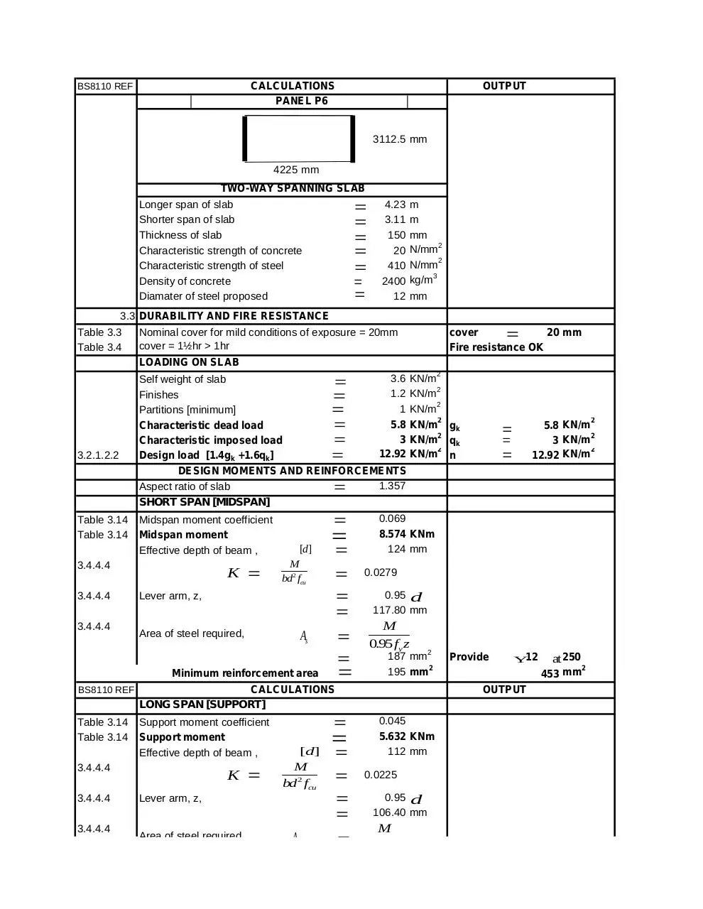
CALCULATIONS
PANEL P6
BS8110 REF
OUTPUT
3112.5 mm
4225 mm
TWO-WAY SPANNING SLAB
Longer span of slab
Shorter span of slab
Thickness of slab
Characteristic strength of concrete
Characteristic strength of steel
Density of concrete
Diamater of steel proposed
4.23
3.11
150
20
410
2400
12
m
m
mm
N/mm2
N/mm2
kg/m3
mm
3.3 DURABILITY AND FIRE RESISTANCE
Table 3.3
Table 3.4
Nominal
for mild conditions
of exposure
= 20mm
Max
firecover
resistance
of 150mm
slab with
20mm
cover = 1½hr > 1hr
LOADING ON SLAB
3.2.1.2.2
3.6 KN/m2
Self weight of slab
1.2 KN/m2
Finishes
1 KN/m2
Partitions [minimum]
5.8 KN/m2 gk
Characteristic dead load
3 KN/m2 qk
Characteristic imposed load
12.92 KN/m2 n
Design load [1.4g k +1.6qk]
DESIGN MOMENTS AND REINFORCEMENTS
1.357
Aspect ratio of slab
3.4.4.4
K
[d]
M
bd2 fcu
Lever arm, z,
Area of steel required,
As
Minimum reinforcement area
BS8110 REF
CALCULATIONS
LONG SPAN [SUPPORT]
Table 3.14
Table 3.14
Support moment coefficient
Support moment
Effective depth of beam ,
3.4.4.4
3.4.4.4
3.4.4.4
K
[d]
M
bd2 fcu
Lever arm, z,
Area of steel required,
2
5.8 KN/m
2
3 KN/m
2
12.92 KN/m
Midspan moment coefficient
Midspan moment
Effective depth of beam ,
3.4.4.4
3.4.4.4
SHORT SPAN [MIDSPAN]
Table 3.14
Table 3.14
cover
20 mm
Fire resistance OK
As
0.069
8.574 KNm
124 mm
0.0279
0.95 d
117.80 mm
M
0.95 fy z
187 mm2
195 mm2
Provide
Y12
OUTPUT
0.045
5.632 KNm
112 mm
0.0225
0.95 d
106.40 mm
M
0.95 fy z
at 250
2
453 mm
Area of steel required,
As
LONG SPAN [MIDSPAN]
Table 3.14
Table 3.14
Midspan moment coefficient
Midspan moment
Effective depth of beam ,
3.4.4.4
3.4.4.4
3.4.4.4
K
Lever arm, z,
Area of steel required,
As
BS8110 REF
DEFLECTION CHECK
Table 3.9
[d]
M
bd2 fcu
M
0.95 fy z
136 mm2
CALCULATIONS
0.95 d
106.40 mm
M
0.95 f y z
103 mm2
y
sreq
sprov
Table 3.10
Modification factor
0.55
Y 12
(477 fs )
2.0
M
)
2
bd
300
mm2
119.7 mm
1.0
453 mm2
187 mm2
*
1
b
2.00
59.86 mm
124 mm
Cracking is controlled by limiting bar spacing.
Maximum spacing allowed for
reinforcement
@
377.1
OUTPUT
112.856 N/mm2
120(0.9
Modified minimum effective depth
3.12.11.2.7 CRACKING
Provide
at 300 2
377 mm
0.0170
fs 23fAA
Design service stress
Y12
0.034
4.256 KNm
112 mm
Basic minimum effective depth
for short span
Moment redistribution factor
Tension reinforcement area provided
Tension reinforcement area required
Provide
372 mm
OK
OK
Download Panel 6
Panel 6.pdf (PDF, 35.7 KB)
Download PDF
Share this file on social networks
Link to this page
Permanent link
Use the permanent link to the download page to share your document on Facebook, Twitter, LinkedIn, or directly with a contact by e-Mail, Messenger, Whatsapp, Line..
Short link
Use the short link to share your document on Twitter or by text message (SMS)
HTML Code
Copy the following HTML code to share your document on a Website or Blog
QR Code to this page

This file has been shared publicly by a user of PDF Archive.
Document ID: 0000610441.