Ventline 2049 VB0156 00 (PDF)
File information
Title: INSTALLATION INSTRUCIONS
Author: Randy Bickel
This PDF 1.4 document has been generated by Acrobat PDFMaker 8.0 for Word / Acrobat Distiller 8.0.0 (Windows), and has been sent on pdf-archive.com on 24/07/2017 at 18:57, from IP address 73.42.x.x.
The current document download page has been viewed 236 times.
File size: 36.14 KB (1 page).
Privacy: public file
File preview
INSTALLATION INSTRUCTIONS
MODEL V2049 Plumbing Vent Cap and Flange
V2049-02, -04 for standard 1 ¼” dia. plastic pipe (1 11/16” O.D.)
V2049-01,-03,-51,-52 for standard 1 ½” dia. plastic pipe (1 29/32” O.D.)
Ventline model V2049 plumbing cap and flange is listed and complies with H.U.D. requirements per sections
3280.602; .603(a) and 3280.611(f)(2),(g) for plumbing vent flashing and plumbing vent caps.
Note: For use on flat or sloped roofs of metal, fiberglass, rubber or shingled surfaces with a maximum of
6/12 pitch. (approximately 27°)
CAUTION! Locate plumbing vent pipe(s) at least three (3) feet or more from any motor driven intake that
opens to habitable areas.
1) Cut clearance hole in roof for vent pipe. Hole size for standard 1 ¼” diameter pipe is approximately 1 7/8” diameter. For
standard 1 ½” diameter pipe, make hole approximately 2 ¼” diameter.
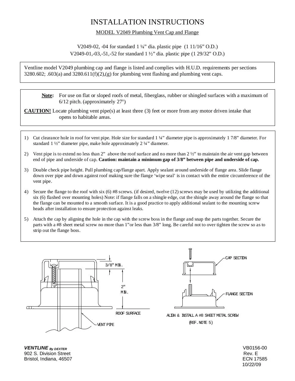
2) Vent pipe is to extend no less than 2” above the roof surface and no more than 2 ½” to maintain the air vent gap between
end of pipe and underside of cap. Caution: maintain a minimum gap of 3/8” between pipe and underside of cap.
3) Double check pipe height. Pull plumbing cap/flange apart. Apply sealant around underside of flange area. Slide flange
down over pipe and down against roof making sure the flange ‘wipe seal’ is in contact with the entire circumference of the
vent pipe.
4) Secure the flange to the roof with six (6) #8 screws. (if desired, twelve (12) screws may be used by utilizing the additional
six (6) flashed over mounting holes) Note: if flange falls on a shingle edge, cut the shingle away around the flange so that
the flange can be mounted to a smooth surface. It is a good practice to apply additional sealant to the mounting screw
heads after installation to ensure protection against leaks.
5) Attach the cap by aligning the hole in the cap with the screw boss in the flange and snap the parts together. Secure the
parts with a #8 sheet metal screw no more than 1”or less than 3/8” long. Be careful not to over tighten the screw so as to
strip out the flange boss.
CAP SECTION
3/8" MIN.
2"
MIN.
ROOF SURFACE
VENT PIPE
VENTLINE By DEXTER
902 S. Division Street
Bristol, Indiana, 46507
FLANGE SECTION
ALIGN & INSTALL A #8 SHEET METAL SCREW
(REF.NOTE 5)
VB0156-00
Rev. E
ECN 17585
10/22/09
Download Ventline 2049 VB0156-00
Ventline_2049_VB0156-00.pdf (PDF, 36.14 KB)
Download PDF
Share this file on social networks
Link to this page
Permanent link
Use the permanent link to the download page to share your document on Facebook, Twitter, LinkedIn, or directly with a contact by e-Mail, Messenger, Whatsapp, Line..
Short link
Use the short link to share your document on Twitter or by text message (SMS)
HTML Code
Copy the following HTML code to share your document on a Website or Blog
QR Code to this page

This file has been shared publicly by a user of PDF Archive.
Document ID: 0000628135.