4035.0000 (PDF)
File information
Title: Microsoft Word - E4035_4035.doc
Author: Schneider
This PDF 1.4 document has been generated by PScript5.dll Version 5.2 / Acrobat Distiller 6.0 (Windows), and has been sent on pdf-archive.com on 21/08/2017 at 09:12, from IP address 72.52.x.x.
The current document download page has been viewed 1062 times.
File size: 228.57 KB (5 pages).
Privacy: public file


File preview
4035.0000 BG
Page: 1 / 5
Wind speed sensor
6
5
7
Issue.
07.05
03.05
02.08
Lo
Lo
Date
Name
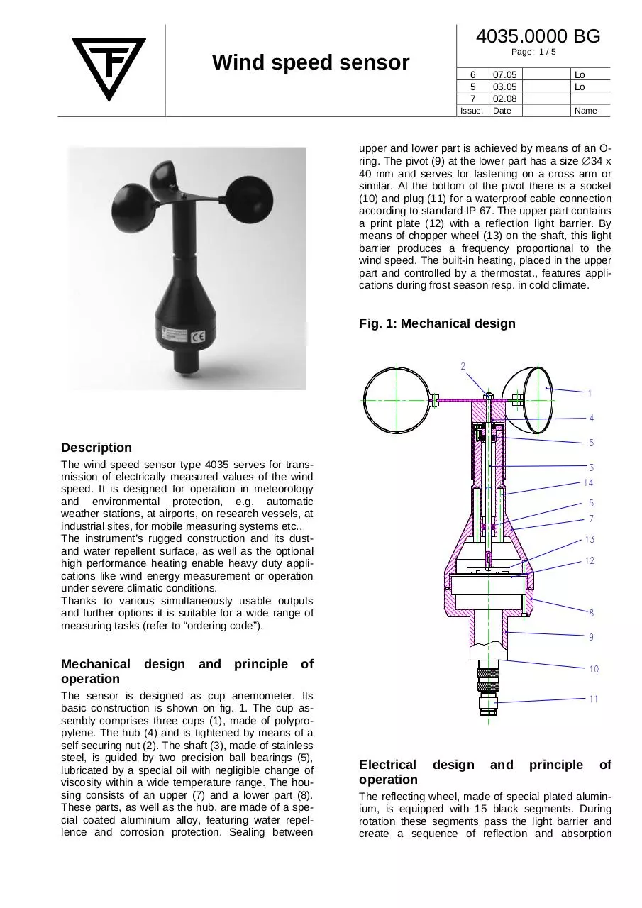
upper and lower part is achieved by means of an Oring. The pivot (9) at the lower part has a size ∅34 x
40 mm and serves for fastening on a cross arm or
similar. At the bottom of the pivot there is a socket
(10) and plug (11) for a waterproof cable connection
according to standard IP 67. The upper part contains
a print plate (12) with a reflection light barrier. By
means of chopper wheel (13) on the shaft, this light
barrier produces a frequency proportional to the
wind speed. The built-in heating, placed in the upper
part and controlled by a thermostat., features applications during frost season resp. in cold climate.
Fig. 1: Mechanical design
2
1
4
5
Description
The wind speed sensor type 4035 serves for transmission of electrically measured values of the wind
speed. It is designed for operation in meteorology
and environmental protection, e.g. automatic
weather stations, at airports, on research vessels, at
industrial sites, for mobile measuring systems etc..
The instrument’s rugged construction and its dustand water repellent surface, as well as the optional
high performance heating enable heavy duty applications like wind energy measurement or operation
under severe climatic conditions.
Thanks to various simultaneously usable outputs
and further options it is suitable for a wide range of
measuring tasks (refer to “ordering code”).
3
14
5
7
13
12
8
9
Mechanical design and principle of
operation
The sensor is designed as cup anemometer. Its
basic construction is shown on fig. 1. The cup assembly comprises three cups (1), made of polypropylene. The hub (4) and is tightened by means of a
self securing nut (2). The shaft (3), made of stainless
steel, is guided by two precision ball bearings (5),
lubricated by a special oil with negligible change of
viscosity within a wide temperature range. The housing consists of an upper (7) and a lower part (8).
These parts, as well as the hub, are made of a special coated aluminium alloy, featuring water repellence and corrosion protection. Sealing between
10
11
Electrical
operation
design
and
principle
of
The reflecting wheel, made of special plated aluminium, is equipped with 15 black segments. During
rotation these segments pass the light barrier and
create a sequence of reflection and absorption
4035.0000 BG
Wind speed sensor
pulses, in a frequency proportional to the wind
speed. Due to precise adjustment of the cup assembly radius there is an exact relation between rotational speed and windrun; the corresponding windrun to one rotation is 1.5 m. As there are 15 segments on the rotating wheel a resolution of 1.5/15 =
0.1 m windrun results and the corresponding frequency output to a measuring range 0…70 m/s is
0…700 Hz. The subsequent electronic circuitry converts this signal to a digital output, resp. further analog outputs (refer to “Technical Data”).
Construction of the heating
The heating consists of a power transistor, controlled by a separate circuitry with temperature sensor.
The high performance heating versions are
equipped with 4 cylindrical heaters (14) with 60 W
max. heating power.
For further signal processing, such as averaging
etc., refer to product group 1, especially datalogger
COMBILOG 1020.
Measuring range:
Max. load:
Starting threshold:
additionally, for version 4035.1---:
analog:
0…60 m/s = 0…1 V
0…60 m/s = 0…20 mA
0…60 m/s = 4…20 mA
Admissible load:
approx. 400 Ω
Admissible ambient
temperature:
-25…+80 °C;
-40…+80 °C with high performance heating
Protection class:
IP 65, when operated upright
Housing material:
Aluminium alloy
Heating:
controlled by thermostat,
max. 7 W
High perf. heating: max. 60 W
Dimensions:
Length:
Cup assembly ∅:
max. housing-∅:
Pivot:
Connection:
Weight:
Measuring cable:
Technical Data
0…70 m/s (0…60 m/s with
analog outputs)
100 m/s
< 0.3 m/s (standard version)
0.21 m/s (sensitive version)
Response length at
v = 5 m/s:
< 2.5 m (standard version)
2.0 m (sensitive version)
Accuracy:
+/-0.2 m/s; at v > 15 m/s
2% of range
Compliances:
WMO Guide No. 8/7th ed.
VDI 3786, T.2, 12/2000
MEASNET
Supply:
Electronics:
4035.0000:
10…30 VDC; < 5 mA at 12 V;
4035.1000:
10…30 VDC; 25…65 mA at 12 V
heating:
10…30 VDC; approx. 7 W
high performance heating:
24 VDC; approx. 60 W
Output:
0…70 m/s = 0…700Hz,
digital:
Open Collector
Page: 2 / 5
approx. 275 mm
approx. 224 mm
80 mm
∅ 34 x 40 mm
12 p., plug and socket, waterand dust proof according to
IP 67
approx. 0.685 kg
LiY(C)Y 0.25 mm2
(not included)
Ordering Code
Wind speed sensor, Frequency output
0..700 Hz, Open Collector; with built-in
heating.
4035.0000
As 4035.0000, but with additional analog outputs 0...20 mA, 4...20 mA and
0...1 V, corresponding 0…60 m/s.
4035.1000
As 4035.0000, but with high performance heating.
4035.0100
As 4035.1000, but with high performance heating.
4035.1100
Sensitive version:
As above mentioned types but with
supplement:
----.--- 1
Operating instructions
Installation:
The wind speed sensor has to be placed at a suitable height (for example 10 m for meteorological
measurement of the ground wind). There is a number of tilting masts of different heights from 5 to 15 m
4035.0000 BG
Wind speed sensor
available for this purpose. Lattice masts up to 80 m
height and various telescopic masts can be supplied
(refer to product group 9). In any case it has to be
taken care to avoid zones of lee or turbulences!
Before mounting the cup assembly has to be fixed
on the shaft of the sensor by means of the nut at the
face.
Page: 3 / 5
Fig. 2: Mounting options
(standard from – stock solutions)
ø224
ø 34
Typ 9023.0000
Adapter
Type 9023.0000
105
Attention:
Do not mount any wind speed sensors without cup
assembly, otherwise ( during rain) water could penetrate into the housing of the sensor!
275
Attention:
Take care that the cup assembly is placed correctly
(white spot to be underneath)!
Mounting is possible on a stand with 35 mm internal
diameter or on an adapter type 9023 (see sketch,
fig.2). In any case a suitable opening (∅35 mm) for
plug connection has to be considered. For mounting
on a cross arm a clamp type 9022 can be used (see
sketch, fig. 2). Using both - wind speed and wind
direction sensor - a U-shaped cross arm, type 9040,
is recommended. Depending on location, the installation of lightning rod, type 9112 or equivalent size,
is advisable!
Power- and measuring lines shall be protected by
suitable over voltage protection devices!
Rohr ø48 mm
Tube ø48 mm
Durchbruch für
Steckerdurchführung
Slotted hole for connection
ø224
Installation on top of wind turbines, ship masts or
similar structures with tilt motion, vibration or other
dynamic force requires a rugged, eventually shock
absorbing, suspension construction.
In this case, please contact us for further consultance.
Klemmfix
Typ 9022.0000
Clamp
Type 9022.0000
Rohr ø33-34 mm
Tube ø33-34 mm
Connection:
Connection has to be carried out according to fig. 3.
Maintenance:
The wind speed sensor type 4035 operates maintenance-free!
Ball bearings, however, are subject to attrition. Their
live time strongly depends on the ambient conditions, such as: average wind speed, pollution, vibration etc.. Therefore an occasional check for plausibility (during low wind speed) is recommended: If a
decrease of sensitivity is detected, the shaft / ball
bearing assembly will have to be replaced.
In case of remote sites with difficult access conditions, for example high measuring towers or wind
turbines, an individual service schedule should be
issued, including preventive replacement of the
bearings, for example every 2 years.
Typ 9112.2000
type 9112.2000
Typ 9040.0000
type 9040.0000
4035.0000 BG
Wind speed sensor
Page: 4 / 5
B2
7G
F
C3
Signalmasse
Signal
ground
K 10
U Heiz.
+
U Heat.
Heizkreis
Heatin circuitry
U Heiz.
0V
U Heat.
5E
U
I (0...20 mA)
I
Stromversorgung
Power supply
6 F
U
I (4...20 mA)
I
Regler
Controller
L 11
U (0...1V)
U
Temperaturfühler
Temp.
Sensor
4035.1000
UB
0V
4D
Stromversorgung
Power supply
*
PullupWiderstand (extern!)
Pullupresistor (extern!)
4035.0000
UB
+
Reflex-Lichtschranke
Reflection light barrier
+UB
Frequenz
Frequence
A1
Steckerpin
Connector pin
Steckerpin
Connector pin
Fig. 3: Block diagram / Connection plan
Heiztransistor
Transistor
(Kugellagerhalterohr)
(Bearing tube)
Steckergehäuse
Kabelabschirmung
Cable screen
Socket
housing
Attention: When several analog outputs are used simultaneously, each output requires a separate ground wire to
be installed directly close to the sensor.
*Pullup resistor not included. The maximum value of the resistor depends on the length of the signal cable. Example for cable length up to 100 m : 20 kΩ. In case of connecting the sensor to the COMBILOG 1020 an external
pullup resistor is not necessary.
ATTENTION: For applications with cable lengths > 5 m between
wind speed sensor and indication instrument, it is recommended
to use the 0…20 mA output, with 50 Ω shunt, in order to avoid
voltage drop due to long distance.
50 Ω
+
-
4035.0000 BG
Wind speed sensor
Page: 5 / 5
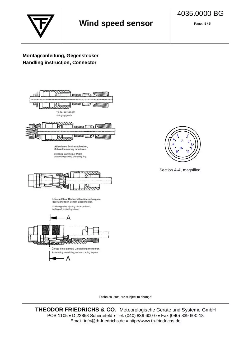
Montageanleitung, Gegenstecker
Handling instruction, Connector
Section A-A, magnified
Technical data are subject to change!
THEODOR FRIEDRICHS & CO. Meteorologische Geräte und Systeme GmbH
POB 1105 • D 22858 Schenefeld • Tel. (040) 839 600-0 • Fax (040) 839 600-18
Email: info@th-friedrichs.de • http://www.th-friedrichs.de
Download 4035.0000
4035.0000.pdf (PDF, 228.57 KB)
Download PDF
Share this file on social networks
Link to this page
Permanent link
Use the permanent link to the download page to share your document on Facebook, Twitter, LinkedIn, or directly with a contact by e-Mail, Messenger, Whatsapp, Line..
Short link
Use the short link to share your document on Twitter or by text message (SMS)
HTML Code
Copy the following HTML code to share your document on a Website or Blog
QR Code to this page

This file has been shared publicly by a user of PDF Archive.
Document ID: 0000653613.