OWNER'S
MANUAL
AND
..;-
INSTALLATION INSTRUCTIONS
OPAR RADIO
MODEL
801
CUSTOM UILT
FOR 1942
PLYMOUTH
DODGE
DE SOTO
CHRYSLER
ELECTRIC
EIGHT TUBE
PUSH BUTTON
--
,
Ii
.
TUNING
,--
---------------
[Jive UhiJ ~tanual
i
-
to lhe Car Owner
�
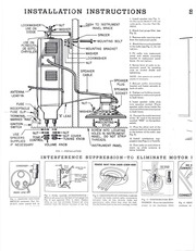
INSTALLATION
o
LOCKWASHER~,
~NUT
USE ON
~WASHER
~t...:
I'
DODGE~-="~:"-
"""'I
t:lI...
c.-..:::D!;;!AS.H
TO~INSTRUMENT
PANEL BRACE
II
SPACER
ii~MOUNTING
,I.1
I
BOLT
':
MOUNTING BRACKET
"
,
WASHER
:.
LOCKWASHER
NUT
I
I.
NOTE-Use
~a;Fif:::;=~~~
SPEAKER
SOCKET
LEAD-IN
::.
::;
" NUT~
:~
'0
I:WASHERL ~oc:::)G;;) ~Q
-
TERMINAL~Wi
MARKED RAD.p";!::~~
''A'LEAD
:',
I
I'
~
~~~
SPE
AKER
-..J.
~~1+6°HN--C:~l:
-=--=--=-~~-=-~-=----=-~-=---t--~--=---------~:~~.N!~-ft_-_-_--=
II
/
USE
SPACERS
SUPPLIED
II
I
I
I'
J,....,
~=~
IF NECESSARY
\SCREW
INTO LOCATING
HOLES IN INSTRUMENT
PANEL. DO NOT STRIP
THREADS.
,g;"
NUT ~1l3I
TONE..#':Jf
CONTROL
4. Attach the mounting bracket
to the radio (see Fig. 1). Do not
tighten.
6. Secure
SPEAKER
PLUG
FUSE
RECEPTACLE
----. FUSE CUP
3. Remove radio opening cover
from the instrurnen t panel.
NUT
@ c NUT COVER
.• TUNING KNOB
VOLUME KNOB
INSTRUMENT PANEL
FIG. I-INSTALLATION
INTERFERENCE
front
of radio
to in-
strurnen t panel by screwing
nuts on control shafts and
tightening.
,::>\0. :'
SPEAKER
CABLE
ANTENNA
2. Attach fuel gauge lilter. (see
Fig. 3).
5. Fit radio into instrument
panel and aUach rnounting
bracket to instrument panel
brace. Do not tighten.
II
111- __
1. Install speaker (see Fig. I).
Model P-14S, use
radio grille, Chrysler Part No.
980524.
On Plymouth
::
~;
USE ON
PLYMOUTH,
DE SOTO,
CHRYSLER
s
INSTRUCTIONS
spacers on control
shafts if necessary.
1. Adjust
radio mounting
bracket and fasten securely to
back of radio.
8. Tighten nut holding mounting bracket to instrument panel
to dash brace.
9. Insert speaker cable plug
into speaker socket. Place
speaker cable along inside the
channel ofthe instrument panel
to dash brace.
-
10. Connect the eyelet terminal
of the "A" lead to the terminal
marked "RAD" on the ignition
switch.
11. Plug the elbow end of the
antenna lead into its receptacle
in the bottom of the radio. (see
Fig. 8).
---
12. Install
interference suppression (see Figs. 2. 4. 5 and 6).
13. Turn radio on and allow to
warm up while antenna is
being installed.
SUPPRESSION-TO
ELIMINATE
MOTOR
REMOVE PAINT fROM UNDER SCREW HEAD
DO ~
CONNEt,
BROWH-YELLOW
TRACER
REMOVE
"ROM
AND
CAUTION:
NOT
ANY
LOWER
Of
DO
CONNECT
WIRES
TO
fUEL
ALL
WIRES
fUEL
GAUGE
TERMINAL
ATTACH
TO
BOTTOM
OF
I
TERMINAL
fiLTER
TERI,4INAL
GAUGE
~
Fig. 3-FUEL
Fig. 2-GROUND lGN[TlON
SWITCH condenser,
Part
No.
61-0177,
under
nearest
bolt
on
GAUGE INTERFERENCE-
Remove all wires from the back of fuel gauge (see
Fig. 3) ani assemble
filter in place.
Replace
wires on two top terminals.
Connect
all wires
removed
from the bottom
terminal
of the fuel
CONNECT
Fig.4-GROUNDING OF CONTROLCABLES
-Ground
the brake control cable, temperature
indicator
tube,
oil line, throttle,
choke
and
speedometer
cable where they enter the dash.
Use the flexible braid in the radio package. Loosen
Fig. 5-DISTRIBUTOR
S.UP.
PRESSOR-&rew the bakelitesup-
Fig. 6--GENJ
pressor
condenser
on
the
distributor
center
on
�
(see Fig. I).
IMPORTANT
leI P-14S, use
sler Part No.
I-MAKE
SURE
OPERATING
.ge filter.
BEFORE
(see
To
be
control
nt panel.
"OFF"SWITCH"
on
the
the
BEEN
MINUTES
radio
extended.
the
With
set at maximum
VOICE,
HAS
ADJUSTMENTS
adjust
fully
SET
TWENTY
MAKING
properly
must
.pe nl nq cover
THE
FOR
the
volume
and the tone
stations
may
.
antenna
control
be
set
up
accurately.
nting bracket
ig. I). Do not
Note:
It is recommended
in metropolitan
set up in a shielded
@
instrument
weak. such
constructed
h mounting
.ment
panel
2-Push
vte n,
place
for best result s
push
buttons
be
where
signals
are
under a viaduct
building .
or in a steel
in the
dial
button
around
and
tune
1400 kilocycles
in a
with
the
manual control (right hand knob). Using a
radio to inby ecrew irtq
shafts
the
85
weak station
FROM
that
areas,
small
screwdriver,
compensator
and
adjust
the proper
for maximum
volume
antenna
(see Fig. 8).
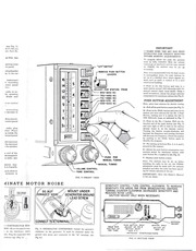
PUSH BUTTON ADJUSTMENT
rs on control
First,
select best stations
for electric
tuning.
A-PuB offthc push button covers (see Fig. 7).
mounting
B-Push
n securely
to
in the DIAL
station
Button,
.ding
1000
rnou nt-
-urnerit
@
panel
turn
Turning
:\g inside
increase
the
:urnentpanel
D-For
proceed
Jo
its receptacle
(see
in
the
button
the push
socket
TONE
FIG.
7-FRONT
the
and
distributor
center
PUSH
HOLE
6-GENERATOR
condenser
ground
ttr-ibutor cap. (Fig. 5.)
Fig. 6.)
in the
manual
station
control.
turning
will
clockwise
Check the station
button
again
to
2,3,4. and 5,
Nos.
compensator
maximum
near
volume
with
radio
must
may
in the
be made
be
set
up
before
car,
but
FINAL
with
the antenna
this
Owner's
Manual
SENSITIVITY CONTROL --TURN CONTROL CLOCKWISE TO INCREASE
SENSITIVITY FOR AREAS FAR FROM BROADCASTING CENTERS.
TURNING COUNTER-CLOCKWISE
DECREASES SENSITIVITY AND
REDUCES NOISE LEVEL.
CAUTION--ADJUST
ONLY WHEN NECESSARY.
SUp·
able. Plug the suppressor into
button
for
IMPORTANT:
Give
to the car owner.
VIEW
0000006-60
000000000
OOOOOO:gqo
000000," -(5,0
("-:(=000=00=0:-)
""'Q)
".0_,
Fig.
7.
installed and after the radio has been opereting for twenty minutes in the car.
CONTROL
MOTOR
the bake1ite sup-
535 to
in Fig.
counter-clockwise
stations
the
adjustment
CONTROL
is
i-DISTRIBUTOR
the
push button covers.
The
installing
and allow to
{lINATE
in the
1 Push
push button No.5 pushed in (see Fig. 8).
VOLUME
the
on
setting up buttons
in like manner.
F-Replace
2,4,5 and 6).
r on
or left to tune
tuned
E-Adjust
sup-
SOR-Screw
as indicated
the frequency
antenna
Note:
antenna
it is within
the frequency.
by pushing
in the DIAL
identify the program.
~
end of the
erence
sure
range
will decrease
the terminal
, the igni Horr
radio.
right
already
-elet terminal
and tune
for the No.
C-Push in the No. 1 button. Pull out the
knurled end of the push button (see Fig. 7)
and
1.0
making
Kilocycle
cable
plug
cket.
Place
N
button
you have selected
on
wire
the
screw
CONDENSER-Install
generator.
and
It
connected
must
to
be
the
the
mounted
H
A"
generator
under
terminal.
the
FO R
PAY-OUT
7Be
OF
TUBE
BUTTON
ADJUST
BUTTON
IZOO
ON LY
ON
NO.5
NEAR
K.C.
ANTENNA
COMPENSATORS
(see
FIG.
8-BOTTOM
VIEW
�
OPERATING
INSTRUCTIONS
You
To Turn the Radio on
DIAL AND BUTTON
ILLUMINATION
CHANGES WITH
TONE CONTROL
VOICE-MUSIC-MELLO
nr.E3
16
14
"OFF"
BUTTON
5
12
10
9
4
ELECTRIC
3
7
TUNING
BUTTONS
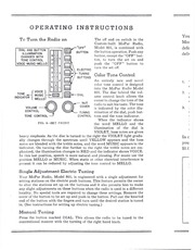
The off and on switch in the
Custom-built
MoPar Radio,
Model 801, is combined with
the button operation. Push any
button, except the "OFF" but- .
ton, to turn the set on and
push the "OFF"
button to
turn the set off.
defe
delis
Color Tone Control
An entirely new and novel
color tone control is designed
5~
1
into the MoPar Radio Model
801. The disc behind the volVOICE
TONE
MUSIC f-f-IMuIICJ
[IOIAm-- DIAL
ume control knob allows the
INDICATOR
MELLO
owner to change the tone of the
NUT
radio to suit his taste. The tone
COVER
is indicated by the color illuVOLUME~
CONTROL
mination of the dial, push butTUNING
TONE CONTROL
CONTROL
tons and the tone indicator.
When the indicator shows
FIG. 9-SET FRONT
the word MELLO and the
illumination
of the dial is
VIOLET, bass notes are given
heavy emphasis. As the disc is turned to the right the VIOLET light gradually changes through the spectrum until YELLOW appears and the bass
notes are blended with the treble notes, and the word MUSIC appears in the
indicator. On turning the disc further to the right the treble notes are emphasized, the illumination changes to RED and the indicator shows VOICE.
In this last position, speech is more natural and pleasing. For music use the
position MELLO or MUSIC. When static or other electrical interference is
present it can be reduced by adjusting the tone control to MELLO.
6
Mac
2
m-{
0=-
Single Adjust:ment Electric Tuning
Your MoPar Radio, Model 801, is engineered with a single adjustment for
setting stations on the electric push buttons. This feature permits the owner
to alter the stations set up on the buttons and it also permits him to make
any slight adjustments on these buttons when the radio is used in a different
locality. No special tools are required to change these settings. Remove the
cover of the button to be set up and push in the button. Pull out the knurled
end of the button with the fingers and turn until the desired station is tuned
in. (See instructions for setting up electric tuning.)
Manual Tuning
Press the button marked DIAL. This allows the radio to be tuned
conventional manner with the turning of the right hand knob.
in the
1.
2.
3.
In c
you
$1.(
�
WARRANTY
AND
SERVICE
Your 1942 Chrysler Corporation MoParCustom
Built Radio,
Model 801, is covered by' the Manufacturer's Warranty against
defects in material and workmanship for a period of 90 days after
delivery of the radio to the original retail purchaser.
"
1
r
I
)
HOW
1
1
:1
TO
OBTAIN
SERVICE
1.
Take your car and radio to your Chrysler Corporation dealer or, if you
are traveling, t~ke\. it to any Chrysler Corporation dealer.
2,
Ask the dealer to (m~ke preliminary checks and such minor repairs as
replacing burnt out fuses, defective tubes, vibrators, repairing loose
outside connections, etc.
3.
If the dealer makes these preliminary checks and tests and is unable to
repair the radio so that it performs satisfactorily, have the dealer remove
the radio from the car and send it to the nearest authorized Warranty
Labor Service Station where free warranty repairs will be made if within
the warranty period as covered by the Warranty policy. When the repairs
are completed, the dealer will re-install the radio in your car..«
e
e
e
,-
s
e
s
n
,-
s
e
..
,
e
I'
I
In case you are traveling, the Chrysler Corporationdealer to whom
you apply for service will render a handling charge not. to exceed
$1.00 for the removal and re-installation of the radio.
s
MAKE CERTAIN THAT WARRANTY
TAG IS FILLED IN
,r
:r
e
.t
e
d
d
e
--'
A Warranty registration tag is furnished with your radio.
This tag must be filled in and attached to your radio by the
car dealer at the time of the retail sale or installation, in
order that the Warranty Labor Service Stations may have
the proper information when you require service under the
Warranty. This is their authorization to render a no-charge
warranty repair.
�
I
SCHEMATIC-MOPAR MODEL-801-PHILCO-C1908
I.F. = 455KC
I
1
I
I
I
I
~
j
~
-+---+~~-----------",~,o,"onOA~C----+--~----"'O~O~o~~---i
I~~
NOTt:·CJoK)f',
IOj AS$rr.6...tO
PART
NO.
1,-0;&.
&urTON
swrfC."
TO P\J$.I1-
ASS(MaLY.
MODEL C-1908 PAnTS LIST
No.
Description
Part xo.
(21) Antenna
Choke. . . . .... ....
.
. .. 65-0~:l7
()
Condenser (250 mmrd.).....
.60-125157
(3) Resistor (l meg. ohrn.)
.33-5101.54
(4)
Condenser (,05 mrr!).....
.01-0101
(5~ 'Push Button Switch
85-0127
(6
Condenser (Image Padder) ....•...............
63-0069
(7
Condenser (55 mmrd.) (Compensator)
61-0149
(81 Condenser (360 mmrn.)
61-01",
(9
Oondenscr
(Part 01 Ant. Padder ABBY.77-07~")
(10
l\lanual Antenna
Coli
(Part 01 Assv. 77-(1%2)
(lOA) Manual Oscllhltor Coli
(Part 01 A~RY.77-091\~)
(IOn) Image Trap Coil.
(Purt or Assy , 77-O!Jr.2)
(J 1)
P. B. No. I Ant. Coil
(Part of Assy. 77-0!)·11)
(l1A) P. B. No.1 Osc. Coil.
(Part Of ABSY. 77-U943)
(12) P. B. NO.2 Ant. Coli
(Part 01 Assv. 77-094:l)
(l2A) P. B. No.2 Osc. Coil. ....••....
(Part Of ABBY.77-094:1)
(13)
P. B. No.3 Ant. Coli
(Part or ABBY.77-0(43)
(l3A) P. B. No.3 Osc, Coli
,
(Part or ASBY. 77-094:1)
(14)
P. B. No. <1 Allt. Col!. ...•......
(Part of Assy. 77-094:1)
(I4A) P. 13. NO.4 Osc. Coil ......•....
(Part 01 Assy. 77-0943)
(15)
P. B. NO.5 Ant. Coli
(Part or Assy , 77-0943)
(l5A) P. 13. No. ;, 08C. Coll.
(Part of Assy. 77-0943)
(lG) On-Oft Swlt ch
.' .. 85-U127
(17)
Antenna Paddr-r Assembly
77-0788
(lR)
Condenser (.05 mtd.)
_•.........
IH-OIOI
(19)
Condenser (.05 mrd.)
_ .. "
61-0111
(201 Senslttvlty
Control. ................•.........
67-0025
(21
Resisto r (1000 ohm)
33-210438
(22
Condenser
(.O!; mtd ..) ....••...................
61-0101
(231 Rexisto r (15000 ohm)
3~-315334
(24
R. F. Plate Coll.
(Part or Assy . 6.0-0421)
(25
It. F. Coupling Condenser
(Part 01 Assy . 65-0421)
(211 I. F. Trap ColI
(Part of ABBY.65-0421)
(27t
1. F. Trap Padder
(Part or Assv. 05-0421)
(28
H~".istO.r (0.1 meg. ohm)
(Part or Assy . .o5-042})
(29
Ht,lstor (100000 ohm)
33-4!Ol ~4
30
PI:<1c Pad'!er
(Part 01 Assy , 65:036~)
31·
ISl I. F. 1:ransrormer
Assembly
ob-03h5
32l
Grid Padeler
(Part of Assv. 65-0:165)
(3:1
Resistor (1 meg. ohm)
33-5101~4
(34
Condenser
(250 mmrd.)
60-1251,,7
(35
Osc, Shunt Col!
_
6.';-0440
(36
condo cnser (250 mrnrd.)
60-12!i157
(37
Resistor (22000 ohm)
33-322334
(38
Plate Padder
(Part of Asay , 65-0366)
(39
2nd l. F. Translormer
Assembly
(l,5-0366
(40)
])I~de pad'!er
(Part or A~sy. (i~-O~~~)
(41)
Resistor (2,,000 ohm)
(Part 01 A.sy. 6.)-00tol»
Reslstor (10 meg , ohm)
33-610154
(43
Condenser (.004 mrri.)
~1-0128
(44
Volume Coo«ol Section
67-0040
61-0101
(45)
Condenser (.05 mId.) ............••.....
Opt. { '61-0170
(46
Reslstor (220000 ohm) .....•................
33-422154
(47
Reststor (1 meg. ohm)
33-510154
(48
Reslstor (6800 ohm)
33-268154
(49
Tone Control Section
(Part 01 AsSY. 67-0040)
(50)
Condenser (.02 mId.)
61-0154
(51) Resistor (4700 ohm)
33-247334
(52) Condenser .(.05 mrd.) ...........•.............
61,-0101
(53)
Resistor (2200 ohm) .... , ..•..........••....
33-222154
Conrlenser (l00 mmtd.) .........•...........
60-1101.57
(55
c.olldenser. (.Olm!fl.)
61-0120.
(56
Condenser (.004 mtd.) .........•.....
"
61-0128
(57
Resistor (220000 ohm)
,
30-4221.14
(51'i
1\('slstor (10 meg , ohm)
31-610154
l
l
(42l
l
(541
(59
Restato
(60)
(61)
(52)
(63)
Resistor (27000 ohm) .....•..•.......•......
Condenser (.OJ mrd.) ........•......•.........
Resistor (470000 ohm) ......•........•......
Resistor (330 ohm) . . . . . . . .. . . . . . . . . . .
Electrolytic Condenser .......•.....
,..
Resistor (470000 ohm) . ,
,
Conden"er (,01 mrrt.). .
.. ..••. . .. .
IIp,;l<tor (220001) oho.)...
Resist or (l000 ohm).....
Condenser (.001l mItt.>'..
(64)
(65)
(66)
(67)
(68)
(69)
r (~:lOOOO ohm).
_
CHRYSLER
FOR"
NO 010070
PHILCO FORr-.·, NO 19 0989·8
3:{-':I:l2154
33-3274:14
61-0120
3:l--147 l!i4
. ... 3~-1.13-!.lR
. .. fll·(j 150
. 3~1-·t4' 154
. .. fil·OlG9
3:1-·12~154
:n-2104'18
. .. fil-0105
No.
(70)
(71)
(72)
(73)
(74)
(7n)
(77)
(71<)
(79)
(SO)
(SI)
(02)
(8:1)
(iH)
(85)
(~Il)
(88)
(89)
(!HI)
(!II)
(U2)
Description
Part No.
OU! put Transformer.....
. . . . . .. . .. . . .
65-0363
Courleuser
(250 mmtd.)
1l0-125157
Yoice 9011
(Part or Speaker Assy. Z3-006Z)
l- leld Call
(Part or Speaker Assy. /3-006,)
Condenser (2:;0 rumru.)
60-125157
Resistor (1000 ohm)
33-210438
Coudcn-r-r
CO,);; ",rd.) ............••..........
61-0153
Power Translormer
r.;)-O~47
Heslstur (IOU ohm) ..........•.....••.......
33-1 1'1'134
It eststor (IOU ohm)
3~l-ll()·j:18
Cuiulenscr
(250 mrntd.) .
. •.........
GO-11.'i157
vruraror
......................•...........
83-00211
Condenser (.5 mfd.)
, .•................
61-nl:14
Condenser 1.5 mtd.) ........•.....•.•........
,61-0137
Vihrntnr
Choke ............•.....••..........
65-0389
Piiol Lamp. .
.....
. ..
. . .. .. .
. .. 34-20r.4
Condenser (2:')0 mmrd.)
_f)O-1251!l7
Condenser (250 IIIl11rd.) ....••••..•
_
GO·l"2t;I.~7
Condenser
(,5 ",r<l.) ..
.
01-0137
Fuse . . . . . .
. . . . . . . . . . . . . . . . . . .. . 45-~.';~9
"A" Choke.
.
:!2-1r.-\4
Speaker {J"I! (OlJlI"""I)
7:!·nOIi7-2
Spcnker Unit «()Il,lon"I).
7:1·!HIf>'-:\
Speaker UnIt (Opt lunul)
,
73-UU6'-4
Speaker Cone Replacement
Kit (73-0067-2)
n l-Olfi4
Speaker Cone Replacement
Klt (n-00fi7-~)
(H-0l65
Speaker Cone Replacement
Kit (73-0067-4) . '" . 91-0228
Generator Condenser
61-01 5/\
Ignition Switch Condenser
61-0177
Distributor
Seal ani! Cover Assembly. . . . ..
. .. 3S-!)5ti2
Fuel Cauz e Filter Kit
"
81-0:1(\8
Braid
,
n.';-OO7:3
Grille Spacer
57-2358FA8
Stud and Bushtnc Assembly (Spkr. l\!tg.)
77-0400
Tone Knob--Chrome
57-1682FA8
Tone Knob-e-Plasttc
77-1011
Nut Cover-Chrome
57-!f;83FAS
Nut Cover-Plastic
77-1012
Knoh Kit
81-0272
Fuse Holder CLip
57-2202FE7
Drive Corel-Pointer
55-14ml
Drtve Cord-Tone
Drum ..........•..........
55-140n
Dlal-e-Plytnout h
55-137 I
Dial-Dodge
: ....•........
55-1370
Dial-DeSoto
...........•..........
,
55-1~09
Dtal-e-Cnrvaler
55-13118
Dlftuslng screen
55-1428
Dlftuslnl! Screen Bracket
57-2242FA3
Br-zr-l-c-Plymouth
, DeSoto. Chrysler
57-2216FA8
Bezel- Dodge
57 -2220 FA R
P. B. Coyer A""y.-PIRln-PI,-mouth
77-0026
P. B. Cover AS8y.-OiT-Plymouth
77-0924
P. B. Cover Assy.-Dlal-Plymouth.
'., , ...•..
77-0925
P. B. Cover AS'Y.-Plaln-Dodge
77-(lM2
P. B. Cover' AssY.-Oft-Dodge
,
77-0973
P. 13. Cover AssY.-Dlal-Dod"e
77-0974
P. B. Cover Assy.-Plaln-DcHoto
77-0\\75
P. B. Cover A'''y.-Off-DeSoto
77-097/\
P. B. Cover Assy.-nlal--OeSolo
77-0n77
~: R: ~g~~~
~~:gm
P. U .. ('on' :Lllcl K(>r A~sy.-:-\u. 2.:-llUfi!!c
77-0fl17
~;':~:=bl~~Ci;;.~~rc~er:::
:: : : :: :: :
P. B. Cover AssY.-Dlal--Clcry,lcr
77-00RO
P. B .. Core nnd Key Assy l-l-1-4-5 Plymouth.
DeSoto, Chrysler
77-0916
P. B .. Core and Key Assy. Dlal und Oft
Plymouth, DeRoto, Chrysler , . . .. .. .
. 77-V~23
P. B._ Cure and Key A:.;:-:y.-()11--Uod~e....
7i-nU15
P. [I.• Core and Key Assy.-i\o.
:l-llo<lge
77-0913
P.ll.
Core and Key Assy.-No.
4--Undl!e
77·()(JI!l
P. B.• Corp ani! Key Assy.-~o.
5-11o,lge
77-on20
P. 13.. Core and Key ASSy.-~(I.
6-!loilg~
77-0!1:!1
P. 13, Core and Key A""Y.-lJlal-Dodge
i7-0H~2
TI1"in~ Sh:,rt .. .....
. . . . . . . .. .
57-22171'.-\:3
Dlu l )\lonn(lng Spr lng .
. .. 57-22181'F11
Fuse Leail Assem hly.
. .....
7i-IlO;;2
Covr-r :-.lIlt
.07-0142FA2R
PRINTED
IN
U. S. A
~
�
INSTRUCTIONS
INSTALLATION
n
LOCKWASHER___.., ~NUT
USE ON
~WASHER
DODGE
~=
__
~~
I:
II
II
..•••
IIII
[l!~'--
I!
On
:~SH
II
II
II
TO INSTRUMENT
PANEL BRACE
~
II
I,
I,
i!
tI
I
II
Plymourh
2. Attach
BOLT
from
opening
6. Secure front of
strument
nuts
cover
panel.
8.
Adjust
radio
and
Tighten
9.
,I NUT~
mounting
fasten
securely
nt-
panel
brace.
speaker
coble
sockel.
coble
along
plug
Place
inside
channel
of the instrument
to do.sh brace,
--==. .l:'o==c:;o""_
0 ~
to
ruou
to instrument
speaker
speaker
/0,
control
on
nut holding
Insert
into
I',WASHERL
the
panel
QI
E§~~~~~~~~§~~
:1
and
of radio.
to da.sh
II
screwing
shafts
NOTE-Use spacers
sllafts if necessary.
ing bracket
I
by
tightening.
~If?~==~~
:1
to in-
radio
panel
control
on
back
•
(see
S. Fit radio into instrument
ponel and attach
mounting
bracket to instrument
panel
brace. Do not ti~hten.
LOCKWASHER
LEAD-IN
VL..I
filter.
Attach the mounting bracket
the radio (see Fig, 1). Do not
tiAhten.
1.
'-
radio
the instrument
bracket
I 0.;;;;1
fuel gouge
3).
:1
TERMINAL~;iL,
MARKED "RAD:',,~
No.
to
BRACKET
NUT
..
Ul
1).
Parr
Chrysler
II
FUSE
Fig.
4.
MOUNTING
WASHER
SPEAKER
CABLE
RECEPTACLE
h,,-,se 1'" 'P
(see
Model P-1JS, use
grille,
980524.
3. Remove
G£GCGO--MOUNTING
I,
ANTENNA
speaker
radio
Fig.
SPACER
:~i
i!;:
.,
SETTING
1. Install
J,....I SPEAKER
-!
10.
Connect
of the "A"
the eyelet
lead
terminal
to the terminal
~:~:~/~~:==~!:::;~--J-----~\--1~i{~!~;gf~rJo
marked
"RAD"
on the ignition
switch.
11.
Plug
the
antenna
elbow
lead
Fig.
SPACERS
SUPPLIED
TONE-""@
CONTROL ~
IF NECESSARY
~
NUT COVER
TUNING KNOB
VOLUME
PANEL. DO NOT STRIP
THREADS,
KNOB
INSTRUMENT
PANEL
12.
Install
Turn
being
INTERFERENCE
interference
(see Figs.
warm
FIG. I-INSTALLATION
of the
of the radio.
(see
8).
pression
13.
end
into its receptacle
in the bottom
radio
up
sup-
2, 4, 5 and 6).
on and
while
allow
antenna
to
is
installed.
SUPPRESSION-TO
FIG,
ELIMINATE
MOTOR
7-FRON',
NOISE
REMOVE PAINT fROM UNDER SCREW HEAD
BROWN'Y£I.LOW
TIt.lCU
A("OVe
ALL
.1AES
'AO""U[LGAUG£
H~"(NAL
ANO ATue"TO
80TTOKHII ••INAL
ANY
WIR£STO
LO· ••.EATtRJ.lIN
•••L
OF FVU GAUGE
Fig.
2-GkOUND
SWITCH
61-0177.
IGNITION
condenser,
under
nearest
Part
bolt
No.
on
Fig. 3--FUEL
GAUGE
INTERFERENCERemove all wires irom the back of fuel gauge (see
Fig:. 3) and assemble
filter in place. Replace
wires on two top terminals.
Conn-ct
all wires
removed from the bottom
terminal
of the fuel
Fig. 4--GROUN
DING OF CONTROL
CABLES
-Ground
the brake control cable, temperature
tube,
oil line, throttle,
choke
and
speedometer
cable where they enter the dash.
Fig.
l.!s~t.h~.flexible b:aid
pressor
indicator
i~ the radio pac~a~~. Loose~
5-DISTRIBUTOR
PRESSOR-Screw
on
the bakelite
the distributor
~UPsupcenter
Fig.
6-GENERATOR
condenser
on
the
CONDENSER-Install
generator.
It
must
be
the
mounted
genera
under
�
 Historical archive . public document