Convertible Rear Window Control Modifications (Jaguar XK8/R)
Jaguar engineers restricted the raising of the convertible rear quarter windows when the
top is down. This document describes a modification to override this restriction and
allow a quick press on the ROOF CLOSE button to raise the windows. This provides for
a quieter ride with less wind buffeting.
Holding the roof close button will raise the top in the normal fashion. (Pressing the roof
lower button already lowers the rear windows when the top is down as a standard
feature).
A second modification retracts the rear quarter windows automatically (auto-down) when
the roof is down and then is closed. This is necessary to prevent damage to the seals of
the convertible top by the rear quarter windows during the top closing sequence.
I recommended that these modifications be used in conjunction with one another.
However, if a window up feature has already been implemented with a dedicated switch
(as descried in Rev. Sam’s You-Tube video); the auto-down modification can be
implemented by itself.
WARNING:
This information is provided in good faith, however it may have unknown consequences.
Any property damage or injury resulting directly or indirectly from use of the information
provided in this document is entirely your responsibility.
A note about T-Taps:
This document describes connection to car wiring with T-Taps. T-Taps are convenient
and easy to use. Unfortunately, they are not as reliable as soldered or crimped
connections. For the utmost reliability of your connections, I recommend the use of
soldered or crimped connections.
�
Part I – ADDING REAR WINDOW RAISE FEATURE (with top down) USING
THE EXISTNG ‘ROOF UP’ BUTTON
Parts List:
Qty 1, DEI 528T Pulse Timer (available on ebay for $10-$12):
http://shop.ebay.com/?_from=R40&_trksid=p5197.m570.l1313&_nkw=dei+528T
&_sacat=See-All-Categories
Qty 1, 12 volt standard automotive relay, SPST or SPDT (about $6 at Radio
Shack http://www.radioshack.com/product/index.jsp?productId=2062477 ), or get
a fog light relay at Advance Auto Parts or Autozone). These relays can be found
cheaper on ebay.
Qty 1, 1N4001 Diode (About $1.00 at Radio Shack,
http://www.radioshack.com/product/index.jsp?productId=2036268 )*
Qty 4, 18-22 ga. Red T-taps
Qty 1, 18-22 ga. Red Inline crimp splice
Qty 1, 18-22 ga. Red ring or spade terminal
18-20 ga. stranded hookup wire (red, white and grey shown, but any colors can be
used)
Misc. size tie wraps
Electrical tape (fabric preferred) and/or heat shrink tubing.
*Note: Some relays have a built in diode. The diode IS REQUIRED here but can be omitted if it
is built into the relay. In either case, be sure to take note of the correct polarity (diode cathode (-)
goes to positive signal for reverse bias).
Procedure:
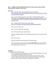
1. Prepare the DEI 528T Pulse timer:
-Cut the orange wire off and tape up or cover the end with heat shrink. Be careful
not to confuse the orange, red and brown wires.
-Cut the blue wire loop and tape up or cover the open ends with heat shrink
-Set the variable resistor with a small screwdriver to the approx. the 8 o’clock
position, which will provide about a 4 second pulse (see below).
�
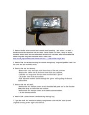
2. Remove shifter trim surround and console wood paneling. Later model cars have a
metal surround that removes with 4 screws. Earlier model cars have a snap on plastic
surround with a metal bracket underneath secured with 4 screws; refer to this thread for
removal tips for the plastic surround with a credit card:
http://www.jaguarforums.com/forum/xk8-xkr-17/1999-shifter-ring-47432/
3. Remove the four screws securing the console storage tray, hinge and padded cover. Set
the cover and tray assembly aside.
4. Remove the rear seat bottom:
-Remove the vinyl stud caps at the lower front of the seat cushions
-Remove the 10mm nuts at the lower front of the seat cushions
-Undo the two snaps over the rear center seat belt latch ‘gloves’
-Lift up the front of the seat cushion
-Push the center seatbelt latches through the ‘glove’ while pulling the bottom
cushion free.
5. Remove the rear seat back.
-Remove the two Phillips screws at each shoulder belt guide and let the shoulder
belt glides drop in front of the rear cushion.
-Remove the two Phillips screws at the under-cushion brackets.
-Lift out the rear cushion.
6. Remove the carpet from the convertible top stowage tray.
7. Open the trunk and remove the battery compartment cover and the audio system
carpeted covering on the right hand sidewall.
�
8. Run two wires from the trunk to the console
-Pass a length of white and a length of violet hookup wire (you can use different
colors if you want, just keep track) through the rear firewall through the same
opening as the convertible top hoses go through. (Note: the violet wire is for use
in Part II.) You can use a piece of solid, stiff building #12 or #14 wire to
temporarily tape the hookup wire to and fish it through the opening. Inside the
cabin route the wires behind the convertible headliner side curtain, down to the
rear seat bottom and across to the console, following and tie wrapping to existing
harnesses where possible. Thread the wires into the rear of the console. Be
careful to route the wire so that it does not get pinched by the convertible top
mechanism (this is easiest if you also remove the rear side trim pieces, but if you
are careful you can do it without removing the rear side trim pieces).
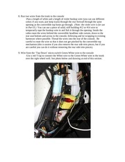
9. Wire from the ‘Top Down’ micro-switch Green-White wire to the console
-Use a red T-tap to connect the White wire to the Green-White wire in the trunk
over the right wheel well. See photo below and drawing at end of this section:
�
10. Pass a wire from the ‘ROOF UP’ switch in the front of the console to the rear of the
console.
-Pass a length of grey wire (you can use different colors if you want, just keep
track) hookup wire front the front of the console to the rear. This can be
accomplished without removing the console by slipping the wire up above the
carpet on the left side of the console.
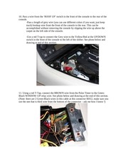
-Use a red T-tap to connect the Grey wire to the Yellow/Red at the UP/DOWN
switch in the front of the console to the left of the shifter. See photo below and
drawing at end of this section:
11. Using a red T-Tap, connect the BROWN wire from the Pulse Timer to the GreenBlack WINDOW–UP relay wire. See photo below and drawing at the end of this section.
(Note: there are 2 Green-Black wires in this cable at this connector RH12, make sure you
use the one that is third wire from the bottom of the connector – ask me how I know !)
�
12. Using a red T-Tap, connect the RED wire from the Pulse Timer and a new red wire to
connect to the relay to the Brown-Red B+ wire at the telephone connector on the left side
of the console. See photo below and drawing at the end of this section.
13. Complete all remaining connections of the relay and pulse timer in the right rear of
the console as shown in the drawing at the end of this section (this can be accomplished
with the console in place (though it might be a bit easier with the console removed). The
relay wiring is shown in the photo below:
14. Tuck the relay and the pulse timer into the right-hand side of the console, against the
carpet.
15. Reinstall the shifter trim surround and console wood paneling.
�
Note: Mount timer in
right rear of console
Trigger
input
Note: Mount relay in right
rear of console
Add a white wire from trunk to
console
Common
Not
connected
1N4001
diode [white
stripe (-) on
this end]
Normally
closed
Not
connected
Blue
Loop
(cut)
Normally
Open
Top Down
Microswitch
GRN/WHT,
connector BT3,
pin 1 (yellow,
18 pin, in trunk above RH
wheel well arch)
Window up
relay GRN/BLK
Connector
RH12, pin 16,
(yellow, 18 pin,
right side
column,3rd pin
from bottom, at
console rear)
Ground
87
(Norm.
Open)
Add a grey wire
console front to
back
87a
86
(Coil)
85
(Coil)
30
(Common)
12v standard
automotive relay
SPST or SPDT with
diode
‘Roof up’ pushbutton
Switch
RED/YEL
(in
front
of console at switch)
+12 V
DEI 528T Pulse
Timer (set for 3-4
second pulse)
Ground to
stud in
console
B+
RED/BRN
Connector RT1, pin
4 (yellow, 14 pin
telephone connector
in left side of
console)
REAR WINDOW RAISE USING
‘ROOF UP’ BUTTON (with top down)
(Jaguar XK8/R)
�
Part II – ADDING ‘AUTODOWN’ REAR WINDOW DROP FEATURE WHEN
CONVETIBLE TOP IS RAISED
Parts List:
Qty 1, DEI 528T Pulse Timer (available on ebay for $10-$12):
http://shop.ebay.com/?_from=R40&_trksid=p5197.m570.l1313&_nkw=dei+528T
&_sacat=See-All-Categories
Qty 1, 12 volt standard automotive relay*, SPST or SPDT (about $6 at Radio
Shack http://www.radioshack.com/product/index.jsp?productId=2062477 ), or get
a fog light relay at Advance Auto Parts or Autozone). These relays can be found
cheaper on ebay.
Qty 2, 18-22 ga. Red T-taps
Qty 2, 14-16 ga. Blue T-taps
Qty 1, 18-22 ga. Red Inline crimp splice
Qty 1, 14-16 ga. Blue ring or spade terminal
18-20 ga. stranded hookup wire (black, green and violet shown, but any colors
can be used)
Misc. size tie wraps
Electrical tape (fabric preferred) and/or heat shrink tubing.
*Note: Some relays have a built in diode. A diode is NOT required here, but will not cause harm
if it is built into the relay, as long as polarity is observed (diode cathode (-) goes to positive signal
for reverse bias).
1. Prepare the DEI 528T Pulse timer:
-Cut the orange wire off and tape up or cover the end with heat shrink. Be careful
not to confuse the orange, red and brown wires.
-Set the variable resistor with a small screwdriver to the approx. the 8 o’clock
position, which will provide about a 4 second pulse.
-Note: DO NOT cut the blue loop
�
2. Skip to step 3 if you have completed Part I. If you are just performing the Auto-down
feature addition only, then follow Part I, only steps 3-8 to gain access for wiring. Also, if
you are just performing the Auto-down feature addition, you only need to run one (violet)
wire in Part I, step 8. The white wire is not needed.
3. Wire the relay to the red/green and black control valve wires in the trunk near the
pump per the drawing at the end of this section and the photo below with blue T-Taps.
Note that the violet wire runs back to the center console (wire was pulled in Part I, step
8).
�
4. Mount the relay to the yellow pump valve connector on the right side of the audio rack
with a tie wrap. See photo below:
5. Using a red T-Tap, connect the BROWN wire from the Pulse Timer to the Green-Blue
WINDOW–DOWN relay wire. See photo below and drawing at the end of this section.
�
6. Using a red T-Tap, connect the RED wire from the Pulse Timer to the Brown-Red B+
wire at the telephone connector on the left side of the console. See photo below and
drawing at the end of this section.
5. Wire the Pulse timer and all remaining connections in the center console per the
drawing at the end of this section.
6. The Delay Timer can rest in the right rear of the console beside the carpet.
7. Carefully dress up all loose wiring with tie wraps and/or electrical tape.
8. After testing the system, re-install the convertible tray carpet, the rear seats, the audio
rack carpeted side cover in the trunk, the battery cover in the trunk and the center console
storage box and cover.
�
Note: Mount timer in
right rear of console
Not
connected
Note: Mount relay near
pump in trunk
Add a violet wire from trunk to
console
Trigger
input
Normally
closed
Normally
Open
87
(Norm.
Open)
Blue
Loop
(do not cut)
87a
86
(Coil)
Ground
+12 V
Common
DEI 528T Pulse
Timer (set for 3-4
second pulse)
Ground to
stud in
console
Window down
relay
GRN/BLU
Connector
RH12, pin 17,
(yellow, 18 pin,
right side
column,2nd pin
from bottom, at
console rear)
B+, RED/BRN
Connector RT1, pin
4 (yellow, 14 pin
telephone connector
in left side of
console)
85
(Coil)
30
(Common)
12v standard
automotive relay
SPST or SPDT
Main Control valve
RED/GRN
wire at pump in trunk,
connector PH3, pin 2, right
side of audio rack
Main Control valve
BLK
Ground wire at pump in trunk,
Connector PH3, pin 1,
right side of audio rack
REAR WINDOW AUTOMATIC
DOWN WHEN CONVERTIBLE TOP
IS RAISED (Jaguar XK8/R)
�
�
 Historical archive . public document