Bell 412EP
Product Specifications
January 2012
Specifications subject to change without notice.
Bell 412EP Product Specification
412 Product Spec.indd 1
1
November 2011
1/31/12 12:07 PM
�
Table of Contents
Publisher’s Notice.............................................................................................................................1
Bell 412EP........................................................................................................................................3
Specification Summary (U.S. Units).................................................................................................4
Specification Summary (Metric Units)..............................................................................................5
BLR Strake and FastFin® ................................................................................................................6
External Dimensions........................................................................................................................8
Bell 412EP Seating and Interior Trim Choices.................................................................................10
Standard Configuration....................................................................................................................12
Optional Accessories........................................................................................................................16
Helicopter Performance Charts........................................................................................................21
Hover Performance Charts...............................................................................................................22
Fuel Flow vs. Airspeed.....................................................................................................................31
Cost of Operations...........................................................................................................................44
Limited Life Components..................................................................................................................47
Paint Schemes.................................................................................................................................49
Bell 412EP Product Specification
February 2012
i
© 2012 Bell Helicopter Textron Inc.
�
Publisher’s Notice
The data presented in this document are general in nature, and have been compiled from Bell Helicopter
Textron Inc. (BHTI) source materials including but not limited to: The Approved Rotorcraft Flight Manual,
Maintenance Manual, Illustrated Parts Catalog, and other engineering design specifications.
This document is intended for the use of BHTI employees, and BHTI independent representatives (international
dealers), and for prospective customers as an aid in determining estimated weight and performance of the
helicopter when configured with equipment for specific missions.
Disclosure, reproduction, or use of any material in this document by persons other than BHTI employees, and
BHTI independent representatives, and prospective customers are forbidden without written permission from
Bell Helicopter Textron Inc.
The listings of Optional Equipment (“Kits”) are subject to revision and change, and also may be different for
specific serial number helicopters or special custom configurations. Please consult the “Notes” column found
in the optional equipment list tables for equipment compatibility. The continuing product improvement process
of BHTI may cause some components, equipment, and compatibility to be changed or replaced.
The specifications, weights, dimensions, and performance data shown in this document are subject to change
without notice.
© 2012 Bell Helicopter Textron Inc.
Bell 206, Bell 407, Bell 429, Bell 412, and JetRanger
are registered trademarks of Textron Innovations Inc.
All rights reserved
Specifications subject to change without notice.
Bell 412EP Product Specification
February 2012
1
© 2012 Bell Helicopter Textron Inc.
�
Page Intentionally Left Blank
© 2012 Bell Helicopter Textron Inc.
2
Bell 412EP Production Specification
February 2012
�
Bell 412EP
RELIABLE, RUGGED AND READY
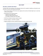
The Bell 412EP is the workhorse of the helicopter industry with a reputation of getting up and going to work
every day in even the most extreme environments.
•• Proven Pratt & Whitney PT6T-3D Twin Pac engines with more than 25 million flight hours in more than
2,000 aircraft worldwide
•• High retirement and overhaul intervals
-- 5,000 hour drive system TBO
-- 4,000 hour engine overhaul interval
-- On-condition composite main rotor blades
•• 25,000 hours between premature engine removals
•• Excellent Category A / JAR OPS 3 capability
•• Rugged fuselage with rollover bulkhead protection and rupture resistant fuel cells
The data set forth in this document are general in nature and may vary with conditions.
For performance data and operating limitations for any specific flight mission, reference must be made to the approved Flight Manual
Bell 412EP Product Specification
February 2012
3
© 2012 Bell Helicopter Textron Inc.
�
Specification Summary (U.S. Units)
Weight
Empty Weight (IFR Std. Config.)
lb
1
Useful Load (Internal, IFR Std. Config.)
Weight
lb
6,964
Maximum Gross Weight (Internal)
11,900
4,936
Maximum Gross Weight (External)
11,900
Maximum External Load
4,500
Performance Summary:
Takeoff, Gross Weight
IGE Hovering Ceiling
OGE Hovering Ceiling
FAA Take Off and Landing Limit, WAT 2
Service Ceiling (AEO)
lb
9,500
10,500
11,900
ISA
ft
17,400
14,300
10,200
ISA + 20 °C
ft
14,400
10,900
6,200
ISA
ft
13,800
10,400
5,200
ISA + 20 °C
ft
10,300
6,050
(11,890 lb @ SL)
ISA
ft
14,000
11,270
7,270
ISA + 20 °C
ft
12,120
9,000
4,990
ISA
ft
19,840
18,760
16,290
(continuous OEI)
ISA
ft
11,450
8,850
5,400
(30 minute OEI) 3
ISA
ft
12,850
10,500
7,600
4,000 ft, ISA
kts
132
130
125
n mi
366
364
358
Maximum Continuous Cruise (true airspeed)
Cruise at Long Range Cruise (LRC) Speed
Range 4
LRC Speed (average true airspeed)
Range 4
LRC Speed (average true airspeed)
Catagory A Takeoff and Landing Ceiling
Elevated Helipad
Endurance at Loiter Speed 4
SL, ISA
4,000 ft, ISA
kts
126
125
122
n mi
414
410
401
kts
131
130
125
ft
6,000
3,400
(11,580 lb @ SL)
ISA + 20 °C
ft
3,750
1,200
(10,800 lb @ SL)
SL, ISA
hr
4.0
3.9
3.6
4,000 ft, ISA
hr
4.3
4.2
3.9
ISA
Engine Ratings: (100% RPM)
Uninstalled
Thermodynamic Power
Engine Rated Power
2 x 950
2 x 900
Standard: Pratt & Whitney PT6T-3D Twin Pac
Takeoff (5 minutes)
SHP
Max Continuous Power
SHP
2 x 950
2 x 800
OEI (2-1/2 minutes)
SHP
1 x 1,140
1 x 1,133
OEI (continuous)
SHP
1 x 970
1 x 1,024
OEI (30 minutes)
SHP
1 x 1,066
1 x 1,079
OEI (continuous)
SHP
1 x 950
N/A
Optional: Pratt & Whitney PT6T-3DF Twin Pac
Transmission Ratings (100% RPM, at mast)
Takeoff (5-minute)
Max Continuous Power
Single Engine
1,370 SHP
1,110 SHP
Limited by Power Available
Fuel (usable)
Type
Capacity
Aviation Turbine
330.5 US Gallons
Note 1 IFR Standard Configuration includes all items listed in the Standard Configuration table of this document as well as twenty-five pounds
(eleven kilograms) of engine oil. Ballast is not included in the standard configuration (ballast is a function of installed equipment).
Note 2 With BLR FastFin® System. Does not apply for Catagory B, 9-passenger seat configuration.
The data set forth in this document are general in nature and may vary with conditions.
For performance data and operating limitations for any specific flight mission, reference must be made to the approved Flight Manual
© 2012 Bell Helicopter Textron Inc.
4
Bell 412EP Production Specification
February 2012
�
Specification Summary (Metric Units)
Weight
Empty Weight (IFR Std. Config.)
kg
1
Useful Load (Internal, IFR Std. Config.)
Weight
kg
3,159
Maximum Gross Weight (Internal)
5,398
2,239
Maximum Gross Weight (External)
5,398
Maximum External Load
2,041
Performance Summary:
Takeoff, Gross Weight
IGE Hovering Ceiling
OGE Hovering Ceiling
FAA Take Off and Landing Limit, WAT 2
kg
4,309
4,763
5,398
ISA
m
5,304
4,359
3,109
ISA + 20 °C
m
4,389
3,322
1,890
ISA
m
4,206
3,170
1,585
ISA + 20 °C
m
3,139
1,844
(5,393 kg @ SL)
ISA
m
4,267
3,435
2,216
ISA + 20 °C
m
3,694
2,743
1,521
Service Ceiling (AEO)
ISA
m
6,047
5,718
4,919
(continuous OEI)
ISA
m
3,490
2,697
1,646
ISA
m
3,917
3,200
2,316
1,219 m, ISA
km/h
244
241
232
(30 minute OEI)
3
Maximum Continuous Cruise (true airspeed)
Cruise at Long Range Cruise (LRC) Speed
Range 4
LRC Speed (average true airspeed)
Range 4
LRC Speed (average true airspeed)
Catagory A Takeoff and Landing Ceiling
Elevated Helipad
Endurance at Loiter Speed
4
SL, ISA
1,219 m, ISA
km
678
674
663
km/h
233
232
226
km
767
757
743
km/h
243
241
232
ISA
m
1,829
1,036
(5,253 kg @ SL)
ISA + 20 °C
m
1,143
366
(4,899 kg @ SL)
SL, ISA
hr
4.0
3.9
3.6
1,219 m, ISA
hr
4.3
4.2
3.9
Engine Ratings: (100% RPM)
Uninstalled
Thermodynamic Power
Engine Rated Power
Standard: Pratt & Whitney PT6T-3D Twin Pac
Takeoff (5 minutes)
kW
2 x 708
2 x 671
Max Continuous Power
kW
2 x 708
2 x 597
OEI (2-1/2 minutes)
kW
1 x 850
1 x 845
OEI (continuous)
kW
1 x 723
1 x 764
OEI (30 minutes)
kW
1 x 795
1 x 805
OEI (continuous)
kW
1 x 708
N/A
Optional: Pratt & Whitney PT6T-3DF Twin Pac
Transmission Ratings (100% RPM, at mast)
Takeoff (5-minute)
1,022 kW
Max Continuous Power
828 kW
Single Engine
Limited by Power Available
Fuel (usable)
Type
Aviation Turbine
Capacity
1,251 liters
Note 3 Increased capability available with optional Pratt & Whitney PT6T-3DF (30 minute OEI Power Kit).
Note 4 Standard fuel, no reserve.
The data set forth in this document are general in nature and may vary with conditions.
For performance data and operating limitations for any specific flight mission, reference must be made to the approved Flight Manual
Bell 412EP Product Specification
February 2012
5
© 2012 Bell Helicopter Textron Inc.
�
BLR Strake and FastFin®
Bell Helicopter has partnered with BLR Aerospace to provide its performance, safety and efficiency-enhancing
FastFin® system as a standard feature on new Bell 412EP aircraft orders. The system incorporates two parallel
stall strips along the tail boom and a reshaped vertical fin. These modifications combine to optimize airflow
around the tail boom, improving the handling, stability and lifting capacity of the Bell 412EP in all environments,
especially high and hot conditions.
The FastFin® system is a combination of two separate modifications, one to the vertical fin and the other to
the tailboom. For clarity, the term FastFin® refers to the BLR modification that changes the shape and contour
of the vertical fin. The term FastFin® System refers to the combined FastFin® and Dual Tail Boom Strake
installation.
The performance benefits of this system include increased tail rotor effectiveness and higher crosswind speed
tolerance at hover in certain conditions. In conditions where the aircraft is currently tail rotor limited the
FastFin® System results in increased Weight-Altitude-Temperature (WAT) capability for takeoff, landing and
in-ground-effect maneuvers, providing substantial improvement in useful load for hot/high operation (See
performance chart below).
14,000
Be
ll
41
M 2EP
ax
G wit
Be
ro h
ss Fa
ll
41
W stF
2E
ei in
gh TM
P
M
tL S
ax
im ys
G
it tem
ro
ss
W
ei
gh
tL
im
it
12,000
Density Altitude (feet)
10000
8,000
6,000
4,000
2,000
0
8,000
9,000
10,000
Gross Weight (lb)
11,000
12,000
Bell 412EP WAT Improvement with FastFin® System
The data set forth in this document are general in nature and may vary with conditions.
For performance data and operating limitations for any specific flight mission, reference must be made to the approved Flight Manual
© 2012 Bell Helicopter Textron Inc.
6
Bell 412EP Production Specification
February 2012
�
Page Intentionally Left Blank
Bell 412EP Product Specification
February 2012
7
© 2012 Bell Helicopter Textron Inc.
�
External Dimensions
Low Skid Gear
Bell 412EP
Low Skid Gear
Optional High Skid Gear WITH AAI FlItEstep®
Bell 412EP
High Skid Gear
Specifications subject to change without notice.
© 2012 Bell Helicopter Textron Inc.
8
Bell 412EP Production Specification
February 2012
�
Optional Emergency Float Gear with AAI FLOATstep™
Bell 412EP
Float Kit
Optional Blade Folding Kit Dimensions
Minimum Hanger Size*
Rotor Not Folded
33.0 ft x 49.6 ft
(10.1 m x 15.2 m)
Minimum Hanger Size*
Rotor Folded
9.5 ft x 55.8 ft
(2.9 m x 17.1 m)
*Allowance should be made for high skid gear, ground wheels,
emply fuel condition and door lip when considering hangar
door width and height
Specifications subject to change without notice.
Bell 412EP Product Specification
February 2012
9
© 2012 Bell Helicopter Textron Inc.
�
Bell 412EP Seating and Interior Trim Choices
Crew Seats -
Two individual energy attenuating seats, fore/aft and up/down adjustable, each equipped
with seat belt, double strap shoulder harness and inertia reel. Available with Grey, Blue,
Red, or Tan upholstery which will match that selected for the cabin.
Passenger Seats - 13 seats offered in three options. (NOTE: Seating option 1 meets the criteria required
by FAA regulations for installation in U.S. registered helicopters. Seating Options 2 & 3
require the addition of the STC Alpine 412 Passenger Shoulder Harness Kit for installation
in U.S. registered helicopters.)
1) Standard Seating - Fabric covered high-backed folding seats with individual seat belts and single strap
shoulder harness and inertia reel, arranged with one row of four (two 2-place benches) forward facing
seats, and one row of five forward facing seats, and two outward facing two place benches (one on
either side of the transmission). Available with Grey, Blue, Red, or Tan upholstery with Black seat belts.
Seats are are also available in all vinyl at additional cost. (210.9 lb [95.7 kg] included in the standard
configuration weight.)
Standard Seating
(Shown with standard interior trim and floor covering)
SEATING OPTIONS 2 AND 3 NOT ILLUSTRATED
2) Utility Seating - Available for U. S. registered helicopters ONLY with addition of STC Alpine 412 Passenger
Shoulder Harness Kit. Nylon covered bench type seating arranged with one row of four rearward facing
seats (behind the crew seats), one row of five forward facing seats (in front of the transmission), and two
outward facing two place benches (one on either side of the transmission). Each seat has an individual
seat belt. Available in Tan or Black. The Utility Seating decreases the standard configuration weight
(-93.3 lb [-42.3 kg], with Alpine Shoulder Harness -59.5 lb [-27.0 kg]).
3) Cushioned Utility Seating - Available for U. S. registered helicopters ONLY with addition of STC Alpine
412 Passenger Shoulder Harness Kit. As in 2) above with the addition of fabric covered cushions,
available in the same colors as the Standard Seating. The Cushioned Utility Seating decreases the
standard configuration weight (-81.1 lb [-36.8 kg], with Alpine Shoulder Harness -47.3 lb [-21.5 kg]).
Specifications subject to change without notice.
© 2012 Bell Helicopter Textron Inc.
10
Bell 412EP Production Specification
February 2012
�
Interior Trim Choices
1) Standard Interior Trim - The Standard Interior Trim is provided as a NO COST OPTION, but is not
included in the Standard Configuration Empty Weight. Included are: Plastic closeouts on upper sidewalls,
window reveals, and cabin headliner; Padded vinyl covering the floor and lower door panels; Lower aft
bulkhead covered with padded vinyl blankets. The hard plastic headliner and closeouts are off-white
in color, and the padded bulkhead blankets and floor covering are color coordinated to match the seat
color selection.The Standard Interior Trim increases the standard configuration empty weight (165.7 lb
[75.2 kg]).
2) Utility Interior Trim - The Utility Interior Trim consists of: Light beige vinyl covered headliner and
bulkhead blankets; Doors painted light beige; Floor painted brown. The Utility Interior Trim is included in
the standard configuration empty weight (33.3 lb [15.1 kg]).
Customized Seating
[Example]
Customized Seating - Custom designed interiors are available from aircraft completion centers to meet the
needs of Corporate or Emergency Medical Service customers.
Specifications subject to change without notice.
Bell 412EP Product Specification
February 2012
11
© 2012 Bell Helicopter Textron Inc.
�
Standard Configuration
(Items Included In List Price)
AIRFRAME
TRANSMISSION/ DRIVE SYSTEM
Aluminum alloy fuselage (over 240 ft [6.8M ]) loading space
3
3
Glass windshields
Main rotor transmission with 4 chip detectors/2 debris
collectors
Vibration isolation / suspension mounts (4)
Tinted overhead windows
Main Lift link (single point suspension)
Dual windshield wipers
Fresh air ventilators with adjustable outlets (8 cockpit and 12
aft cabin)
Bleed air heater and defroster with air noise suppression
Cargo tie-down fittings (51 aft cabin floor)
42º gearbox (sight gage and magnetic drain plug/chip
detector)
90º gearbox (sight gage and magnetic drain plug/chip
detector)
Hydraulic pumps for controls (2 independent systems)
Map and data case
Transmission oil cooler
Cabin fire extinguisher (2)
Swingout jettisonable doors (2 for forward cabin)
Sliding doors (2 for aft cabin access with 2 emergency exit
panels on each door)
Swingout panels for extended access to aft cabin (2)
Fixed step on skids for entry to forward cabin (2)
Retractable steps for aft cabin access (2)
Baggage compartment in tail boom (over 28 ft3 [0.8M3], 400 lb
[181kg] capacity).
Skid-type landing gear with replaceable wear shoes
Mooring and jacking fittings (4)
POWER PLANT
Pratt & Whitney of Canada PT6T-3D “Twin Pac” (1800 SHP)
Automatic governors (2)
Magnetic chip detectors
Torque limiter
Fuel System (330.5 US Gal [1251 liter] usable, rupture
resistant cells and breakaway vent fitting)
Pumps on engines and submerged in fuel tanks
Fuel filter assembly
Oil coolers (2)
Fire detection system (2)
External attachment fittings (16)
Fire extinguisher system (2)
Semi-monocoque tailboom
RPM warning system
BLR Strake and FastFin®
Elevator (airspeed / spring-cartridge controlled)
Tail skid
Hinged cowling
Starter-generators (2)
Power turbine RPM control actuators
Cargo hook provisions
Combining gearbox with chip detector
AUDIO
Two station aft intercom system w/crew interface
ROTORS & CONTROLS
Soft-in-plane flex beam hub with four fiberglass blades
Main rotor droop restraint
Separate firewall protection for each engine
Overriding clutches (2)
Extended Engine Exhaust Deflectors
COMMUNICATIONS & NAVIGATION
720 Channel VHF rec/trans transceiver (KTR-908)
Pendulum vibration absorbers
VHF antenna
Semi-rigid, two bladed all-metal tail rotor
All controls hydraulically boosted (dual systems for main rotor)
Force trim system and artificial feel (electrically set)
Dual controls
2 Headsets (pilot & copilot)
2 Intercomunication Panels (ICS) (pilot & copilot)
Emergency Transmit Switch
Horizontal Situation Indicator
Cyclic stick centering
Attitude Director Indicator
RPM governor selector control
Attitude and Heading Reference Systems (2)
Manual engine torque matching and trim
Dual Digital Three axis AFCS (2 flight control computers)
Cockpit voice recorder provisions
Rotor brake
Specifications subject to change without notice.
© 2012 Bell Helicopter Textron Inc.
12
Bell 412EP Production Specification
February 2012
�
Standard Configuration (continued)
FLIGHT & ENGINE INSTRUMENTS
FLIGHT & ENGINE INSTRUMENTS (continued)
Flight Director Nav Coupler (3-axis)
Master warning lights on the instrument panel draw attention
to:
Free air temperature indicator
AL-300 Data Display
Pitot static system with electric pitot heat
Altimeter (barometric)
Radar altimeter #1
RPM
Eng 2 Out
Eng 2 Fire
Eng 1 Out
Eng 1 Fire
Baggage Fire
Cyclic
Over torque
centering
(mast)
IFR EQUIPMENT
Clock, digital quartz chronometer
Co-pilot clock
Hourmeter
Distance Measuring Equipment (DME) (KDM-706)
Magnetic compass, pilot’s standby
IFR FAA kit
Airspeed indicator
Automatic Direction Finder (ADF) (XDF-806)
Rate of climb indicator
Nav receiver #1 VOR/LOC with HB/HSI (KNR-634)
Turn and slip indicator
Nav receiver #2 VOR/LOC with HSI (KNR-634)
Triple tachometer (rotor and engines)
VHF-AM Comm #2 radio (KTR-908)
Dual hydraulic press/temp indicator (2)
Transponder (MST67)
Gas producer tach indicator (2)
Co-pilot instruments (FAA)
Triple torque indicator (Eng 1, Eng 2, mast)
Standby attitude indicator
Engine oil-temp/press indicator (2)
ELECTRICAL
Turbine inlet temperature indicator (2)
Generator (2) (30 volt, 200 ampere DC startergenerator
derated to 150 amperes)
Fuel pressure indicator
Transmission oil-temp/press indicator
Inverters (2), (450 volt ampere single phase, solid state)
Dual DC and AC voltmeters
Nickel cadmium battery (40 ampere hours)
Dual DC loadmeter
Battery over-temp warning
Fire detection warning (3)
Generator voltage regulators
Combining gearbox oil-temp/press indicator
Instrument (integral) lights (white)
Flight data recorder provisions
Navigation lights
Caution & Warning System - Master caution light on panel
draws attention to the pedestal mounted annunciator panel
when worded segments illuminate:
Landing light-retractable
Anticollision light (2)
Engine oil press (2)
DC generator (2)
Tritium lighted emergency exit signs
Trans oil press
Gen overheat (2)
Cockpit lights (2)
Trans oil temp
AC inverter (2)
Dome lights (3)
Comb box oil press
External power
External power receptacle
Comb box oil temp
Battery switch
Twin ignition and starting systems
Chip detectors (5)
Battery temp
Seat belt sign
Fuel boost (2)
Hydraulic
Passenger step lights
Fuel filter (2)
Door locks
Baggage compartment light & fire sensor
Fuel valve (2)
Heater
Utility cabin lights (removable)
Fuel low (2)
Part sep off (2)
Fuel X feed
Rotor brake (2)
Emerg gov manual (2)
Caution panel
PAINT
Markings for high visibility M/R blades (white & orange)
Specifications subject to change without notice.
Bell 412EP Product Specification
February 2012
13
© 2012 Bell Helicopter Textron Inc.
�
Standard Configuration (continued)
MISCELLANEOUS
Covers, tail pipe, turbine air inlet, and pitot tube
Flight bag
Ground handling wheels, hydraulically activated
Manuals: Aircraft log, Engine log, Engine operations, Flight,
Maintenance & Overhaul Manual, Illustrated Parts Catalog
Tie-down assemblies, main rotor & tail rotor
INTERIOR TRIM
Choice of Standard or Utility Interior Trim.
Standard; Rigid three-piece headliner in cabin, padded
fiberglass floor covering, bulkheads, trimmed with
cream-colored plastic and color-coordinated vinyl coated
fiberglass, cabin doors trimmed with plastic, special
soundproofing, seat upholstered with foam and fabric.
Selection of fabric colors. Not included in Standard
Configuration Weight, increases empty weight 165.6
pounds (75.1 kilograms) when installed.
Utility; Beige soundproofing blankets on bulkheads and
overhead; doors painted beige, floor painted brown.
Included in Standard Configuration Weight (approximately
32.6 pounds, 914.8 kilograms).
Specifications subject to change without notice.
© 2012 Bell Helicopter Textron Inc.
14
Bell 412EP Production Specification
February 2012
�
Page Intentionally Left Blank
Bell 412EP Product Specification
February 2012
15
© 2012 Bell Helicopter Textron Inc.
�
Optional Accessories
[Kits listed below are compatible with the FAA IFR 3-axis / non-EFIS configuration except as individually noted]
Additional kits and STC items may be available for factory installation.
Please consult sales or contract personnel regarding special needs prior to selection of final configuration.
Kit Description
Wt (lb)
Wt (kg)
Notes
FIXED STEP LEFT HAND
11.7
5.3
1, 2
FIXED STEP RIGHT HAND
11.6
5.3
1, 2
HEAVY DUTY HIGH SKID GEAR w/o STEPS
18.5
8.4
1, 3
HEAVY DUTY HIGH CROSS TUBES FOR EMER. FLOATS
3.8
1.7
EMERGENCY FLOATS (provisions)
51.0
23.2
4
EMERGENCY FLOATS /RESERVOIR & NOSE
97.5
44.2
4
EMERGENCY FLOATS (L.G. w/ FLOATS & PWR STEPS)
168.8
76.6
1, 4
HEATED WINDSHIELD
9.8
4.4
1
EXPANDABLE BOLTS - MAIN ROTOR
3.0
1.4
AIRFRAME
FUEL KIT - MANIFOLD DRAIN
0.3
0.1
-16.1
-7.3
SEAT BELT SIGN - STD INTR
0.3
0.1
SEAT BELT SIGN - DLX INTR
0.3
0.1
AUX FUEL PROVS
5.4
2.5
5
AUX FUEL, 16.3 GAL LH
20.2
9.1
5
AUX FUEL, 16.3 GAL RH
20.2
9.1
5
AUX FUEL, 81.7 GAL LH (REQUIRES REMOVAL OF 2 OUTBOARD-FACING PAX SEATS)
50.3
22.8
5
AUX FUEL, 81.7 GAL RH (REQUIRES REMOVAL OF 2 OUTBOARD-FACING PAX SEATS)
50.3
22.8
5
5
9 CELL FUEL SYS
INDICATOR, FUEL QTY, AUX FUEL
-0.1
0.0
TOLERANT FUEL
98.5
44.7
EFIS (ELECTRONIC FLIGHT INSTRUMENT SYSTEM)
113.4
51.4
1, 6
4-AXIS DDAFCS W/ DUAL FLIGHT DIRECTOR
26.4
12.0
7
PRIMUS 700 WEATHER RADAR
49.1
22.3
7
PRIMUS 700 WEATHER RADAR W/ EFIS
54.6
24.8
7
ENCODING ALTIMETER
0.1
0.0
1, 7
RADAR ALTIMETER #2
12.2
5.6
7
CABIN PA SYSTEM (NON-EFIS)
9.3
4.2
CABIN PA SYSTEM (EFIS)
9.5
4.3
OVERHEADD AUXILIARY BUSSING
0.1
0.0
ALT VOICE WARNING (FOR RAD ALT 2 SHIPS)
1.3
0.6
ALT VOICE WARNING
1.4
0.6
COPILOT RADAR ALTIMETER KIT
3.0
1.3
COPILOT RADAR ALTIMETER KIT (EFIS)
3.0
1.3
AIR DATA COMPUTER
3.2
1.5
ELT PROVISIONS
1.8
0.8
AVIONICS
Specifications subject to change without notice.
© 2012 Bell Helicopter Textron Inc.
16
Bell 412EP Production Specification
February 2012
�
Optional Accessories (continued)
Kit Description
Wt (lb)
Wt (kg)
Notes
MAX CONTIN PWR W/O 30 MIN OEI
0.0
0.0
1
MAX CONTIN PWR W/ 30 MIN OEI
0.0
0.0
1
3DF ENG-INC OEI 30 MIN OEI, W/O MCP
0.0
0.0
1
3DF ENG-INC OEI 30 MIN OEI W/ MCP
0.0
0.0
1
3D 30 MIN OEI W/O MCP
0.0
0.0
1
3D 30 MIN OEI W MCP
0.0
0.0
1
ENG INSTRM KIT - MAX CONT POWER
0.1
0.1
1
10.3
4.7
1
-177.0
-80.3
1,9
10
ENGINE
ENVIRONMENT
HEAVY DUTY HEATER
EQUIPMENT
6-PLACE LITTER KIT (NON-FAA AIRCRAFT, PAX SEATING REMOVED)
CARGO HOOK PROVISIONS
6.9
3.1
CARGO HOOK (COMPLETE)
40.7
18.5
CARGO HOOK EQUIPMENT
33.8
15.4
10
INTERNAL RESCUE HOIST (5 PAX SEATS REMOVED)
106.8
48.5
11
INTERNAL RESCUE HOIST (SLING ONLY)
172.9
78.4
N/A
N/A
GROSS WEIGHT TOWING PULLER EQUIPMENT (LOOSE)
SAR PROVISIONS (INTERFACE KIT ONLY)
3.8
1.7
7
-96.2
-43.6
1,9
INTERNAL HOIST PROVISIONS
8.9
4.0
HOIST CABLE GUARD
5.2
2.4
3-PLACE LITTER KIT (FAA AIRCRAFT) + ATTENDANT SEAT (AIRLINE PAX SEATS
REMOVED)
INCREASED GENERATOR CAPACITY
0.7
0.3
TRANSMISSION POWER TAKEOFF
27.9
12.7
1
GROSS WEIGHT TOWING PULLER PROVISIONS
2.9
1.3
CREW DOOR MIRROR
0.3
0.1
53 AMP-HOUR BATTERY KIT
15.8
7.2
1,6,7
53 AMP-HOUR BATTERY KIT W/ FLOATS
15.8
7.2
1,6,7
BATTERY CABLE KIT FOR WEATHER RADAR PROVS
1.4
0.6
1,6,7
FRAHM DAMPER, INSTR PNL
18.7
8.5
UTILITY SEATS (RAG AND TUBE-NOT FAA, REMOVES STD AIRLINE SEATS)
-93.3
-42.3
SEAT CUSHIONS (FOR RAG & TUBE SEATS)
12.2
5.5
INTERIOR
ONE MAN SEAT (2 FWD FACING REPL 4 LH/RH OUTBOARD FACING)
1,12
-2.5
-1.1
1
165.7
75.2
1
0.0
0.0
13
ALPINE SHOULDER HARNESS KIT (FOR UTILITY SEATS)
33.8
15.3
12
WIRE STRIKE - HIGH SKID - RECOMMENDED KIT - SEE NOTE
19.2
8.7
14
WIRE STRIKE - LOW SKID - RECOMMENDED KIT - SEE NOTE
18.7
8.5
14
STD DELUXE INTERIOR (HARD PLASTIC)
PAINT
MARKINGS FOR HIGH VISIBILITY M/R BLADES (WHITE & ORANGE)
STC’s EQUIPMENT
Specifications subject to change without notice.
Bell 412EP Product Specification
February 2012
17
© 2012 Bell Helicopter Textron Inc.
�
Optional Accessories (continued)
Kit Description
Wt (lb)
Wt (kg)
180.0
81.6
-30.9
-14.0
0.0
0.0
Notes
Credits EQUIPMENT
GROUND HANDLING WHEELS
PAINT
NO EXTERIOR PAINT
WHITE PAINT ONLY
EXPLANATORY NOTES
All equipment kits require Provision Kits prior to installation
Notes: For commonality, notes shown below are identical in Product Specification and Price List.
(1) Price and / or Weight includes credit for basic ship hardware removed.
(2) FAA requires either standard electric powered steps or fixed steps to conduct passenger carrying operations.
Weight change is for replacement of low skid gear powered steps. Fixed step actual weight 11.7 lb (5.3 kg) each.
Fixed steps not compatible with emergency pop out floats or rescue hoist.
(3) FAA requires either standard electric powered steps or fixed steps to conduct passenger carrying operations. For
powered passenger steps add 21.5lb (9.8kg); For fixed steps add 23.4lb (10.6kg).
(4) For a complete installation of Emergency Floats (412-706-004-153, -163, and -165) are required.
(5) Aux Fuel Provision Kit (412-706-112-101) must be installed prior to or concurrently with installation of kits
(412-706-112-103, -104, -105, and -106). Aux fuel tank kits can be installed in any combination with maximum of
two per aircraft (one per side). Total auxiliary fuel volumes possible are 81.7, 163.4, 98.0, 32.6, and 16.3 gallons.
(6) EFIS is compatible with 4-axis level 1&2; See Table on AFCS configuration page. EFIS requires inst allation of
53 AMP Hour Battery. Different Kits are required for Std. Landing Gear(412-706-059-101), Floats
(412-706-059-103), and an additional kit is required if Weather Radar(412-706-059-105) is installed.
(7) 4-Axis Level 2 AFCS configurations require FAA IFR configuration and installation of additional equipment kits.
See the tables on the AFCS configuration pages for items required and installed weight.
(8) 3-Axis Level 1 AFCS configurations requires FAA IFR configuration and installation of additional equipment kits.
See the tables on the AFCS configuration pages for items required and installed weight.
(9) The 412-706-006-105 Litter Kit is FAA certified equipment. The 205-706-047-011 Litter Kit is not FAA certified.
Weights are for all standard seats removed and attendant seat(s) installed.
(10) Cargo Hook Provisions (212-706-103-103) must be installed prior to Cargo Hook Equipment (212-706-103-119).
(11) Internal rescue hoist (214-706-003-107) requires installation of provisions (412-706-011-105), Cable Guard
(412-706-017-113), and Two Station Aft Cabin ICS (412-706-012-111).
(12) Utility Seating is available on U. S. registered helicopters ONLY with the addition of the STC’d Alpine 412
Passenger Shoulder harness Kit.
(13) Standard or High Visibility Main Rotor Blade Paint to be specified by Sales Order.
(14) The Wire Strike Kit is a RECOMMENDED extra cost option. The customer must specify on the Purchase
Agreement for the WSPS Kit NOT to be installed
P.O.R. - Priced On Request.
STC Kits - Select Supplemental Type Certificated Optional Equipment Kits are available for installation at the
Bell Helicopter Textron factory. Please contact your Bell Helicopter Sales Representative for availability
and pricing information.
Specifications subject to change without notice.
© 2012 Bell Helicopter Textron Inc.
18
Bell 412EP Production Specification
February 2012
�
Bell 412EP Standard Dual Digital AFCS Configurations*
IFR (FAA) Configuration
(lb)
(kg)
DUAL CONTROL
25.6
11.6
CO-PILOT CLOCK KIT
0.2
0.1
DME (KDM-706A)
6.5
2.9
FAA / IFR KIT
3.2
1.5
ADF (KDF-806)
7.1
3.2
NAV 1 VOR/LOC w/ GS (KNR-634)
10.1
4.6
NAV 2 VOR/LOC w/ GS (KNR-634)
7.8
3.5
VHF COMM / RADIO #2 (KTR-908)
6.3
2.9
TRANSPONDER (KXP-756)
10.5
4.8
CO-PILOT INSTRUMENTS (FAA) (3-AXIS)
17.7
8.0
STANDBY ATTITUDE INDICATOR
8.8
4.0
RADAR ALTIMETER #1
6.6
3.0
110.4
50.1
(lb)
(kg)
Installed Weight IFR (FAA) Configuration
Level 1
3-Axis Dual
With Flight Directors, without EFIS
3-AXIS DDAFCS w/ DUAL FD
Installed Weight Level 1.
6.5
2.9
116.8
53.0
* Other configuration can be developed to meet specific customer equirements.
Dual Digital AFCS Operating Parameters
Level 1 : Standard Flight Director modes; ALT, IAS, VS, HDG, NAV, ILS, BC, VOR APR, GA.
Level 2 : Same as Level 1 Plus; Simultaneous ALT and IAS, Simultaneous IAS andVS, Altitude Pre-Select
(ALTPRE) [barometric level-off], Hover Hold (RAD ALT), ILS decelerate, and YAW Autotrim.
Specifications subject to change without notice.
Bell 412EP Product Specification
February 2012
19
© 2012 Bell Helicopter Textron Inc.
�
Bell 412EP Optional Dual Digital AFCS Configurations
LEVEL 2
4-AXIS DUAL
With Flight Directors, with EFIS
(lb)
(kg)
See Level 1, 3-AXIS DUAL, With Flight Directors, w/o EFIS **
116.8
53.0
EFIS (4-TUBES)
113.4
51.4
BATTERY, 53 AMP-HR
15.8
7.2
4-AXIS DDAFCS
26.4
12.0
AIR DATA COMPUTER
3.2
1.5
392.4
178.0
Installed Weight
* Other configuration can be developed to meet specific customer requirements.
** The FAA IFR configuration and Level 1 (3-axis dual) is required in addition to the equipment listed above.
Note:
- EFIS, Air Data Computer and Radar Alt #1 are required for all 4-axis configurations.
Specifications subject to change without notice.
© 2012 Bell Helicopter Textron Inc.
20
Bell 412EP Production Specification
February 2012
�
Helicopter Performance Charts
Specifications subject to change without notice.
Bell 412EP Product Specification
February 2012
21
© 2012 Bell Helicopter Textron Inc.
�
Hover Performance Charts
Combined WAT Limited and Hover Capability
10 or More Passenger Seats
And 9 or Less Passenger Seats
PT6T-3D Engine
Engine Continuous Power
Transmission Takeoff Power
The following Hover Performance Charts are presented in a revised format which should simplify the comparison
of Weight Altitude Temperature (WAT) limited Take Off and Landing Capability and the Hover Capability for
known favorable wind conditions.
IGE Hover Performance
Combined WAT Limited and Hover Capability
10 or More Passenger Seats
And 9 or Less Passenger Seats
PT6T-3D Engine
Engine Continuous Power
Transmission Takeoff Power
BLR Strake & FastFin®
Example
Wanted
IGE hover weight for the 9 or less passenger seat configuration
Known
Pressure Altitude = 10,000 ft
OAT = 20 °C
Method
Step 1. To determine the IGE hover weight, enter the IGE hover capability chart at a pressure altitude of
10,000 ft. Move horizontally to the right to intersect the 20 °C line. Move vertically down to read
a hover capability of 10,500 lb.
Step 2. To determine the WAT limited gross weight, enter the IGE WAT limitation chart at 20 °C. Drop
vertically down to intersect the 10,000 ft pressure altitude line. Move horizontally to the right to
intersect the 9 or less passenger seats WAT line. Move vertically up to read 10,140 lb. This is the
WAT limited gross weight.
Step 3. The lower of Step 1 and Step 2 will result in a correct IGE hover weight of 10,140 lb.
The data set forth in this document are general in nature and may vary with conditions.
For performance data and operating limitations for any specific flight mission, reference must be made to the approved Flight Manual
© 2012 Bell Helicopter Textron Inc.
22
Bell 412EP Production Specification
February 2012
�
Hover Performance Charts (continued)
IGE Hover Capability
Compare hover capability with
WAT limitations. The lower of the
two gross weights determined is
the correct hover performance.
IGE Hover WAT Limitation
The data set forth in this document are general in nature and may vary with conditions.
For performance data and operating limitations for any specific flight mission, reference must be made to the approved Flight Manual
Bell 412EP Product Specification
February 2012
23
© 2012 Bell Helicopter Textron Inc.
�
Hover Performance Charts (continued)
OGE Hover Performance
Combined WAT Limited and Hover Capability
10 or More Passenger Seats
And 9 or Less Passenger Seats
PR6T-3D Engine
Engine Continuous Power
Transmission Takeoff Power
BLR Strake & FastFin®
Example
Wanted
OGE hover weight for the 9 or less passenger seat configuration
Known
Pressure Altitude = 10,000 ft
OAT = 20 °C
Method
Step 1. To determine the OGE hover weight, enter the OGE hover capability chart at a pressure altitude
of 10,000 ft. Move horizontally to the right to intersect the 20 °C line. Move vertically down to read
a hover capability of 9,300 lb.
Step 2. To determine the WAT limited gross weight, enter the OGE WAT limitation chart at 20 °C. Drop
vertically down to intersect the 10,000 ft pressure altitude line. Move horizontally to the right to
intersect the 9 or less passenger seats WAT line. Move vertically up to read 9,550 lb. This is the
WAT limited gross weight.
Step 3. The lower of Step 1 and Step 2 will result in a correct OGE hover weight of 9,300 lb.
The data set forth in this document are general in nature and may vary with conditions.
For performance data and operating limitations for any specific flight mission, reference must be made to the approved Flight Manual
© 2012 Bell Helicopter Textron Inc.
24
Bell 412EP Production Specification
February 2012
�
Hover Performance Charts (continued)
OGE Hover Capability
Compare hover capability with
WAT limitations. The lower of the
two gross weights determined is
the correct hover performance.
OGE Hover WAT Limitation
The data set forth in this document are general in nature and may vary with conditions.
For performance data and operating limitations for any specific flight mission, reference must be made to the approved Flight Manual
Bell 412EP Product Specification
February 2012
25
© 2012 Bell Helicopter Textron Inc.
�
Service Ceiling
Twin Engine Operation at Maximum Continuous Power
The data set forth in this document are general in nature and may vary with conditions.
For performance data and operating limitations for any specific flight mission, reference must be made to the approved Flight Manual
© 2012 Bell Helicopter Textron Inc.
26
Bell 412EP Production Specification
February 2012
�
Service Ceiling
OEI @ Continuous Power
Standard PT6T-3D Engine
The data set forth in this document are general in nature and may vary with conditions.
For performance data and operating limitations for any specific flight mission, reference must be made to the approved Flight Manual
Bell 412EP Product Specification
February 2012
27
© 2012 Bell Helicopter Textron Inc.
�
Increased OEI Performance Option
Kit No. 412-706-050
(PT6T-3DF Engine with OEI 30 Minute Power)
Installation of Kit No. 412-706-050 provides the use of an additional 55 shaft horsepower (engine rated power)
under one engine inoperative conditions, for a period of thirty minutes.
Bell 412EP Power Ratings
Engine Ratings: (100% RPM)
Uninstalled
Thermodynamic Power 1
Engine Rated
Power 2
2 x 950
2 x 900
Standard: Pratt & Whitney PT6T-3D Twin Pac
Takeoff (5 minute)
SHP
Max Continuous Power
SHP
2 x 950
2 x 800
OEI (2-1/2 minutes)
SHP
1 x 1,140
1 x 1,133
OEI (continuous)
SHP
1 x 970
1 x 1,024
Takeoff (5 minute)
SHP
2 x 950
2 x 900
Max Continuous Power
SHP
2 x 950
2 x 800
OEI (2-1/2 minutes)
SHP
1 x 1,140
1 x 1,133
OEI (30 minutes)
SHP
1 x 1,066
1 x 1,079
OEI (continuous)
SHP
1 x 950
N/A
Optional: Pratt & Whitney PT6T-3DF Twin Pac
Note 1: Sea Level, ISA Day
Note 2: Uninstalled mechanical limit
The kit consists of new Gas Producer gauges, ITT gauges, Engine/Transmission Torque gauge, and
placards for the instrument panel. There is no increase in empty weight of the aircraft. Performance increase
data is presented on the next page.
The data set forth in this document are general in nature and may vary with conditions.
For performance data and operating limitations for any specific flight mission, reference must be made to the approved Flight Manual
© 2012 Bell Helicopter Textron Inc.
28
Bell 412EP Production Specification
February 2012
�
Service Ceiling
OEI @ 30 Minute Power
* Optional PT6T-3DF Engine Kit *
[Rotorcraft Flight Manual Supplement-56.3 or 56.4 ]
The data set forth in this document are general in nature and may vary with conditions.
For performance data and operating limitations for any specific flight mission, reference must be made to the approved Flight Manual
Bell 412EP Product Specification
February 2012
29
© 2012 Bell Helicopter Textron Inc.
�
Page Intentionally Left Blank
© 2012 Bell Helicopter Textron Inc.
30
Bell 412EP Production Specification
February 2012
�
Fuel Flow vs. Airspeed
ISA & ISA + 20 °C
PRATT & WHITNEY CANADA
PT6T-3D ENGINE
NOTE: The best allowable cruise speed is either long range cruise speed (LRC, or when speed is
limited by Maximum Continuous Cruise Power (MCP) or VNE, the maximum speed permitted .
The data set forth in this document are general in nature and may vary with conditions.
For performance data and operating limitations for any specific flight mission, reference must be made to the approved Flight Manual
Bell 412EP Product Specification
February 2012
31
© 2012 Bell Helicopter Textron Inc.
�
Fuel Flow
Twin Engine Operations (97% RPM) Zero Wind
Sea Level Pressure Altitude
OAT = 15 °C (ISA)
The data set forth in this document are general in nature and may vary with conditions.
For performance data and operating limitations for any specific flight mission, reference must be made to the approved Flight Manual
© 2012 Bell Helicopter Textron Inc.
32
Bell 412EP Production Specification
February 2012
�
Fuel Flow
Twin Engine Operations (97% RPM) Zero Wind
2,000 Feet Pressure Altitude
OAT = 11 °C (ISA)
The data set forth in this document are general in nature and may vary with conditions.
For performance data and operating limitations for any specific flight mission, reference must be made to the approved Flight Manual
Bell 412EP Product Specification
February 2012
33
© 2012 Bell Helicopter Textron Inc.
�
Fuel Flow
Twin Engine Operations (97% RPM) Zero Wind
4,000 Feet Pressure Altitude
OAT = 7 °C (ISA)
The data set forth in this document are general in nature and may vary with conditions.
For performance data and operating limitations for any specific flight mission, reference must be made to the approved Flight Manual
© 2012 Bell Helicopter Textron Inc.
34
Bell 412EP Production Specification
February 2012
�
Fuel Flow
Twin Engine Operations (97% RPM) Zero Wind
6,000 Feet Pressure Altitude
OAT = 3 °C (ISA)
The data set forth in this document are general in nature and may vary with conditions.
For performance data and operating limitations for any specific flight mission, reference must be made to the approved Flight Manual
Bell 412EP Product Specification
February 2012
35
© 2012 Bell Helicopter Textron Inc.
�
Fuel Flow
Twin Engine Operations (97% RPM) Zero Wind
8,000 Feet Pressure Altitude
OAT = -1 °C (ISA)
The data set forth in this document are general in nature and may vary with conditions.
For performance data and operating limitations for any specific flight mission, reference must be made to the approved Flight Manual
© 2012 Bell Helicopter Textron Inc.
36
Bell 412EP Production Specification
February 2012
�
Fuel Flow
Twin Engine Operations (97% RPM) Zero Wind
10,000 Feet Pressure Altitude
OAT = -5 °C (ISA)
The data set forth in this document are general in nature and may vary with conditions.
For performance data and operating limitations for any specific flight mission, reference must be made to the approved Flight Manual
Bell 412EP Product Specification
February 2012
37
© 2012 Bell Helicopter Textron Inc.
�
Fuel Flow
Twin Engine Operations (97% RPM) Zero Wind
Sea Level Pressure Altitude
OAT = 35 °C (ISA + 20)
The data set forth in this document are general in nature and may vary with conditions.
For performance data and operating limitations for any specific flight mission, reference must be made to the approved Flight Manual
© 2012 Bell Helicopter Textron Inc.
38
Bell 412EP Production Specification
February 2012
�
Fuel Flow
Twin Engine Operations (97% RPM) Zero Wind
2,000 Feet Pressure Altitude
OAT = 31 °C (ISA + 20)
The data set forth in this document are general in nature and may vary with conditions.
For performance data and operating limitations for any specific flight mission, reference must be made to the approved Flight Manual
Bell 412EP Product Specification
February 2012
39
© 2012 Bell Helicopter Textron Inc.
�
Fuel Flow
Twin Engine Operations (97% RPM) Zero Wind
4,000 Feet Pressure Altitude
OAT = 27 °C (ISA + 20)
The data set forth in this document are general in nature and may vary with conditions.
For performance data and operating limitations for any specific flight mission, reference must be made to the approved Flight Manual
© 2012 Bell Helicopter Textron Inc.
40
Bell 412EP Production Specification
February 2012
�
Fuel Flow
Twin Engine Operations (97% RPM) Zero Wind
6,000 Feet Pressure Altitude
OAT = 23 °C (ISA + 20)
The data set forth in this document are general in nature and may vary with conditions.
For performance data and operating limitations for any specific flight mission, reference must be made to the approved Flight Manual
Bell 412EP Product Specification
February 2012
41
© 2012 Bell Helicopter Textron Inc.
�
Fuel Flow
Twin Engine Operations (97% RPM) Zero Wind
8,000 Feet Pressure Altitude
OAT = 19 °C (ISA + 20)
The data set forth in this document are general in nature and may vary with conditions.
For performance data and operating limitations for any specific flight mission, reference must be made to the approved Flight Manual
© 2012 Bell Helicopter Textron Inc.
42
Bell 412EP Production Specification
February 2012
�
Fuel Flow
Twin Engine Operations (97% RPM) Zero Wind
10,000 Feet Pressure Altitude
OAT = 15 °C (ISA + 20)
The data set forth in this document are general in nature and may vary with conditions.
For performance data and operating limitations for any specific flight mission, reference must be made to the approved Flight Manual
Bell 412EP Product Specification
February 2012
43
© 2012 Bell Helicopter Textron Inc.
�
Introduction
Cost of Operations
Bell Helicopter Textron Inc.’s cost of operations data for current production helicopters is based on information
from Bell Helicopter operators and service facilities. BHTI’s Product Support organization accumulates cost data from a
diverse group of operators - large, small; sub-polar, subtropical; inland, coastal; corporate, charter. This information is
analyzed to generate sample data for each production model which are averages of the field experience. BHTI intends to
continue monitoring actual costs to enable annual updates of the data to maintain its currency.
The following discussion is provided to review the variables involved in the helicopter’s direct and indirect cost of
operations as well as its cost of ownership.
The total cost of helicopter ownership and operation involves both direct and indirect costs. The direct costs are those
which are incurred essentially by the flight hour and include:
•• Fuel, Lubricants
•• Basic Airframe Maintenance
•• Powerplant Maintenance
The indirect costs are not directly dependent upon the number of hours flown and include:
•• Insurance
•• Facilities (hangar, workshop, etc.)
•• Crew Compensation
•• Financial Factors (depreciation, investment tax credit, financing costs, etc.)
Sample direct operating cost data is available for each current production model. Detailed estimates for total costs
relating to specific operations are available through the BHT regional marketing manager or corporate office using input
data supplied by customer/prospect.
Direct Costs
Fuel, Lubricants
A typical average value of fuel and lubricant costs is included in the sample data provided for each model. Fuel consumption
depends upon speed, temperature, externally-mounted accessories, sling loads, etc. A band of approximately 10% more
or less than sample value will cover these factors for normal operations. Fuel pricing varies considerably based on where
the fuel is purchased geographically and whether it is purchased retail or in bulk. The sample cases use average retail
purchase price prevalent at the time of the sample data are prepared.
Basic Airframe Maintenance
Airframe maintenance is divided into four categories:
•• Periodic Inspections
•• Overhauls
•• Replacement of Retirement Parts
•• Unscheduled
Periodic inspections include those inspection tasks, with their part requirements, listed in the Maintenance Manual for each
model. Man hours for periodic inspections can vary from the sample value provided because of differences in personal
experience, tool and parts availability, facilities, environmental effects such as extremes in working temperatures. Man
hour costs/hour are also variable among the Authorized Service Centers as a result of differences in local costs, overhead
expenses and volume of work. The sample value is an average of costs per hour at Authorized Service Centers at the
time of publication.
Overhauls include removal, disassembly, inspection, parts replacement, reassembly and reinstallation of certain
components/assemblies at the periods stated in the BHTI Maintenance Manual. Overhaul man hour and parts requirements
are subject to considerable variation depending upon the helicopter’s operations and environments. The sample data
reflect average values.
Specifications subject to change without notice.
© 2012 Bell Helicopter Textron Inc.
44
Bell 412EP Production Specification
February 2012
�
Retirement parts are those which are subject to disposal after an operating time stated in the Maintenance Manual.
These are normally components of the rotors/control systems which are subject to oscillatory loads and are designed and
tested for use over a finite number of flight hours rather than on their condition. The replacement at the required intervals
requires some labor which is included in the man hour data in the sample.
Unscheduled maintenance encompasses labor and parts replacement for major maintenance not covered under the
formal Maintenance Manual requirements for inspections and overhauls. It also includes those additional maintenance
requirements imposed by the manufacturer through issue of Service Bulletins.
The sample data for periodic inspections provide for some minor unscheduled maintenance tasks resulting from the
inspection.
Powerplant Maintenance
The powerplant (engine [s]) requires periodic inspection and overhauls. The overhaul periods are based on the number
of operating hours or on the number of cycles, whichever is the first limit to be attained. Start cycles are a factor because
thermal cycles are important in the design of the turbine engine’s rotating components. Overhauls are performed by the
engine manufacturer and/or at authorized facilities. Powerplant overhaul can be performed for the engine as a unit, or in
some cases for individual modules. (Modules can be gearbox, compressor, turbine, for example.) Each module can have
its own overhaul period. Modular overhaul can be cost-effective for some operations and its use should be evaluated.
Engine or module exchanges can be made in lieu of overhaul. For details, contact the engine manufacturer or his
authorized distributors/service centers. The sample costs are based on an average exchange. The powerplant may also
require unscheduled maintenance (unscheduled removals for repair, parts replacement).
Indirect Costs
Insurance:
Insurance rates are based on a number of factors including claim experience, type of
operations, and crew qualifications. Rates can be obtained from insurance agent/broker.
Facilities:
Facilities can include hangar, workshop, parts storage area, tools, ground support
equipment and administrative area as appropriate to the specific operation.
Crew Compensation:
The number of aircrew personnel depends on the individual operation; i. e., whether the
normal crew consists of one or two pilots, hours per day flown, backup requirements for
illness, vacation, etc. Bell Helicopter regional marketing managers can advise typical local
costs for estimation purposes.
Financial Factors:
Funding a helicopter purchase can be accomplished in a variety of ways, including cash,
short term note, long term note, partnership, etc. For investment accounting, several
depreciation methods also exist; straight line, double declining, sum of the years digits,
etc. Value of resale is a significant factor.
Miscellaneous Factors:
Staff expenses (other than aircrew and direct maintenance personnel), utilities, office
expenses, etc.
Ownership Analysis Program
Bell Helicopter Textron uses the most recently published edition of the Life Cycle Cost computer program provided by
Conklin & de Decker Associates, Inc. to determine ownership costs for an operators planned period of utilization for the
aircraft. Conklin’s Rotorcraft Analysis Office may be contacted at: Phone; (817) 277-6403 or Fax; (817) 277-6402.
Bell Helicopter’s regional marketing managers or corporate office personnel will be able to assist in preparing an ownership
analysis which is customized for our customers specific individual conditions and needs.
Specifications subject to change without notice.
Bell 412EP Product Specification
February 2012
45
© 2012 Bell Helicopter Textron Inc.
�
Sample - Direct Cost of Operations - US Dollars Per Flight Hour
Operator Overhaul
Fuel, Lubricants
Fuel: (Note 1)
$452.00
Lubricants:
$4.52
Airframe Direct Maintenance
Labor: (Note 2)
Scheduled Inspections (Note 3)
$38.08
Scheduled Retirements (Note 4)
0.32
Scheduled Overhauls (Note 5)
8.08
Provision for Unschedule Maintenance and Service Bulletins
1.23
On-Condition Maintenance
32.26
Parts:
Scheduled Inspections (Note 3)
12.98
Scheduled Retirements (Note 4)
122.74
Scheduled Overhauls (Note 5)
55.81
Provision for Unschedule Maintenance and Service Bulletins
25.79
On-Condition Maintenance
176.45
Powerplant Direct Maintenance
Pratt & Whitney Model PT6T3D - Quanity 2
Mfr. Estimate of Engine Cost Per Hour (Note 6)
308.42
BHT Est of Miscellaneous Line Maintenance (Labor - Note 3)
29.27
Total Average Cost Per Hour
$1,272.91
Notes: (1) Calculated at 113 GPH at $4.00 per gallon.
(2) Labor rate assumed at $80.00 per hour.
(3) Based on 600 FLT HRS/YR
(4) Based on 100% Life
(5) Based on 100% TBO
(6) Engine estimate assumes utility application, 2 engine cycles per hour, benign environment (no allowance for severe
operation, environment, or conditional repairs).
Other assumptions:
Basic VFR helicopter with no optional equipment installed mature helicopter; no warranty
considerations
Component Overhaul Intervals (Hours)
Swashplate & Support
2,500
Rotor Brake Quill
2,500
T/R Gearbox
5,000
Hub & Sleeve Assy
2,500
Transmission
5,000
T/R Driveshaft Hangar
3,000
T/R Hub Assembly
2,500
Intermediate Gearbox
5,000
Driveshaft Couplings
5,000
Mast Assembly
5,000
Starter Generator (2)
1,000
Notes: (1) To obtain average overhaul cost, combine the interim inspection and overhaul costs or refer to R:Base database.
(2) The Bell 412EP has three servo actuators. The average part cost and labor hours relate to all three actuators, not
each actuator.
(3) Added a provision for replacement of the T/R Spiral Bevel Gear which became O.C. in ‘95. Used ratio of overhaul
costs to total assembly cost times the list price of the gear (7635/41604*2903=533); 533 +7635 = 8168.
Specifications subject to change without notice.
© 2012 Bell Helicopter Textron Inc.
46
Bell 412EP Production Specification
February 2012
�
Limited Life Components
Part Number
Component
Life in Flight
Hours
Life in
RIN
Qty per
a/c
MAIN ROTOR COMPONENT
412-010-101-129
Yoke Assembly
5,000
2
412-010-190-105
Spindle
10,000
4
412-010-149-111
Pitch Horn
10,000
4
412-010-124-109
Retention Bolt
5,000
4
412-010-137-103
Retention Bolt
5,000
4
412-010-185-109
Damper Bridge
15,000
4
412-010-111-103
Fitting
5,000
4
412-010-170-105
Damper Bridge
10,000
4
MAIN ROTOR CONTROLS
412-010-425-113
Pitch Link Tube
5,000
2
412-010-425-129
Pitch Link Tube
5,000
2
412-010-182-101
P/L Rod End Brg Upper
5,000
4
412-310-400-101
P/L Rod End Brg Lower
5,000
4
412-010-406-115
Swashplate Link Assy
5,000
2
412-010-445-105
Drive Hub Assy
10,000
1
412-010-403-113
Rephasing Lever Assy
5,000
2
412-010-403-117
Rephasing Lever Assy
5,000
2
412-010-405-111
Drive Link Assy
5,000
2
412-010-407-117
Swashplate Outer Ring
10,000
1
412-010-453-105
Swashplate Support Assy
5,000
1
204-010-404-001
Gimbal Ring Assy
9,000
1
204-011-408-10
...
 Historical archive . public document