BO54J15640D
SFP+ 10G 1550nm 40KM CDR
RoHS Compliant Optical Transceiver
SFP+ 10G 1550nm Single mode Optical Transceiver with CDR
Features
Description
The BlueOptics© BO54J15640D SFP+ transceiver is a
high performance, cost effective module supporting a
datarate up to 10Gbps with 40 Kilometer link length
on single mode fiber.
10Gb/s serial optical interface compliant to
802.3ae 10GBASE-ER
EML laser transmitter
BlueOptics© transceivers are 100% compliant with
SFP+ Multi-Source Agreement (MSA).
PIN photo-detector
Build in CDR on TX and RX
Hot-pluggable SFP+ footprint compliant to
SFF-8431
Duplex LC/UPC
interface
2-wire interface for management
Metal enclosure, for lower EMI
RoHS compliant and lead-free
Single +3.3V power supply
Compliant with SFF-8472
Case operating temperature
All BlueOptics© SFP+ transceivers are always
equipped with digital diagnostic function compliant to
MSA SFF-8472.
Using digital diagnostic, BlueOptics©
transceivers provide the following real
information:
-
SFP+
time
Supply voltage
Laser bias current
Laser average output power
Laser received input power
Temperature
The transceiver consists of five sections: An EML
transmitter, a PIN photodiode, a trans-impedance
preamplifier (TIA), the LD Driver and the digital
diagnostic function.
-
Applications
10GBase-ER/EW
Ethernet / Fiber Channel
Switch to Switch Interface
Router/Server Interface
Other optical links
-1-
type
pluggable
Commercial: 0°C to +70°C
Extended: -10°C to +80°C
Industrial: -40°C to +85°C
optical
�
BO54J15640D
SFP+ 10G 1550nm 40KM CDR
RoHS Compliant Optical Transceiver
Warnings
Order Information
Handling Precautions: This device is susceptible to
damage as a result of electrostatic discharge (ESD). A
static free environment is highly recommended.
Laser Safety: Even small radiation emitted by laser
devices can be dangerous to human eyes and lead to
permanent eye injuries. Be sure to avoid eye contact
with direct or indirect radiation.
Part No.
Temp.
BO54J15640D
DDM
0°C to +70°C
BO54J15640DEX
-10°C to +80°C
BO54J15640DIN
-40°C to +80°C
Regulatory Compliance
Feature
Electrostatic
Warranty
Standard
Co.
- IEC/EN 61000-4- 2
Discharge (ESD)
Every BlueOptics© transceiver comes with a 5 year
replacement warranty and lifetime support.
For a warranty inquiry, please contact your CBO sales
representative.
This warranty only covers the first user of the
equipment.
Important Notice
Performance figures, data and any illustrative
material provided in this data sheet are typical and
must be specifically confirmed in writing by CBO
before they become applicable to any particular order
or contract. In accordance with the CBO policy of
continuous improvement specifications may change
without notice.
The publication of information in this data sheet does
not imply freedom from patent or other protective
rights of CBO or others.
Further details are available from any CBO sales
representative.
Installation
Before installation attach an ESD-preventive wrist to
ensure not to damage the transceiver or hardware.
BlueOptics© BO54J15640D can be installed in any
Small Form Factor Pluggable+ (SFP+) port. You can
install the BO54J15640D regardless if the system is
powered on or off, because it is hot-swappable.
Insert the transceiver into the SFP+ port and remove
the dust cap.
You can now connect your cable.
-2-
Electromagnetic
- FCC Part 15 Class B EN 55022
Interference (EMI)
- Class B (CISPR 22A)
Laser Eye Safety
- FDA 21CFR 1040.10, 1040.11
- IEC/EN 60825-1, 2
Component
Recognition
- IEC/EN 60950, UL
RoHS
- 2002/95/EC
EMC
- EN61000-3
Class 1
�
BO54J15640D
SFP+ 10G 1550nm 40KM CDR
RoHS Compliant Optical Transceiver
1. Absolute Maximum Ratings
Parameter
Storage Temperature
Storage Ambient Humidity
Symbol
Ts
HA
Min.
-40
5
Typ.
Max.
85
95
Unit
ºC
%
2. Recommended Operating Conditions
Parameter
Symbol
Case Operating Temperature
Ambient Humidity
Transmission Distance
Coupled Fiber
Min.
0
-10
-40
5
Tcase
HA
Typ.
Max.
70
80
85
70
40
Unit
ºC
Note
BO54J15640D
BO54J15640DEX
BO54J15640DIN
%
KM
Single mode fiber
9/125µm SMF
3. Electrical Interface Characteristics
Parameter
Power Supply Voltage
Signal Input Voltage
Transmitter
Input differential impedance
Single ended data input swing
Transmit Disable Voltage
Transmit Enable Voltage
Transmit Disable Assert Time
Receiver
Differential data output swing
Data output rise time
Data output fall time
LOS Fault
LOS Normal
Power Supply Rejection
Symbol
Vcc
Icc
Min.
3.13
Rin
Vin,pp
VD
VEN
Typ.
3.3
Max.
3.47
360
100
Vout,pp
tr
tf
VLOS
fault
VLOS
norm
PSR
Unit
V
mA
Note
Ω
1
180
Vcc-1.3
Vee
700
Vcc
Vee+0.8
10
mV
V
V
µs
400
28
28
Vcc-1.3
850
VccHOST
mV
Ps
Ps
V
Vee
Vee+0.8
V
100
mVpp
2
3
4
4
5
5
6
Notes:
1. Internally AC coupled.
2. Or open circuit.
3. Into 100Ω differential termination.
4. 20-80%
5. LOS is an open collector output. Should be pulled up with 4.7KΩ on the host board.
6. All transceiver specifications are compliant with a power supply sinusoidal modulation of 20 Hz to 1.5 MHz
up to specified value through the power supply filtering network shown on page 23 of the Small Form factor Pluggable (SFP) Transceiver Multi Source Agreement (MSA), September 14, 2000.
-3-
�
BO54J15640D
SFP+ 10G 1550nm 40KM CDR
RoHS Compliant Optical Transceiver
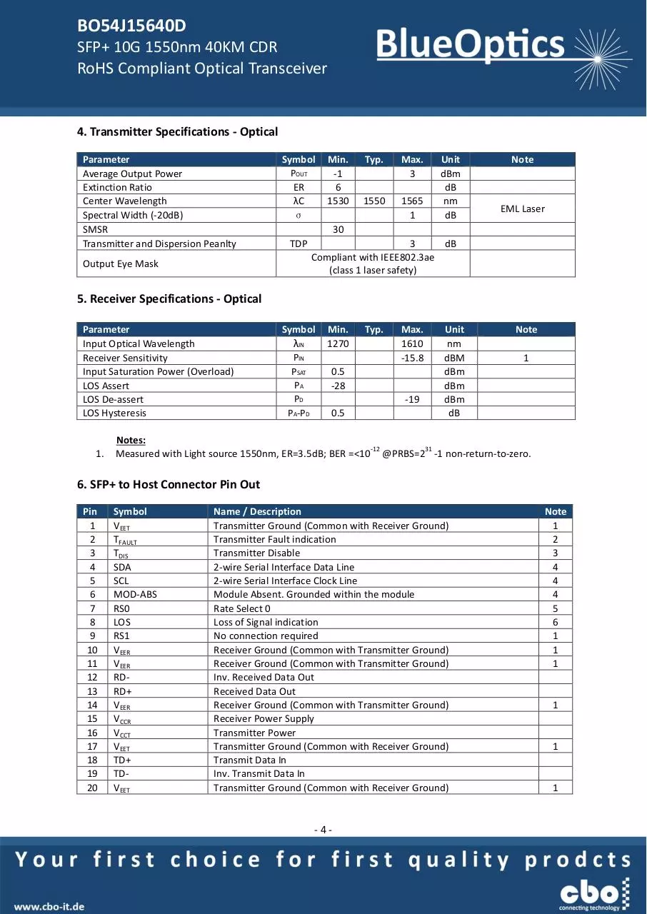
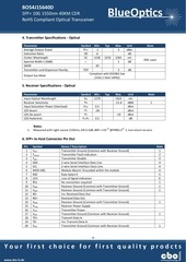
4. Transmitter Specifications - Optical
Parameter
Average Output Power
Extinction Ratio
Center Wavelength
Spectral Width (-20dB)
SMSR
Transmitter and Dispersion Peanlty
Symbol
POUT
ER
λC
σ
Min.
-1
6
1530
Typ.
Max.
3
1550
1565
1
Unit
dBm
dB
nm
dB
Note
EML Laser
30
TDP
Output Eye Mask
3
dB
Compliant with IEEE802.3ae
(class 1 laser safety)
5. Receiver Specifications - Optical
Parameter
Input Optical Wavelength
Receiver Sensitivity
Input Saturation Power (Overload)
LOS Assert
LOS De-assert
LOS Hysteresis
1.
Symbol
λIN
PIN
PSAT
PA
PD
PA-PD
Min.
1270
Typ.
Max.
1610
-15.8
0.5
-28
-19
0.5
Unit
nm
dBM
dBm
dBm
dBm
dB
Note
1
Notes:
-12
31
Measured with Light source 1550nm, ER=3.5dB; BER =<10 @PRBS=2 -1 non-return-to-zero.
6. SFP+ to Host Connector Pin Out
Pin
1
2
3
4
5
6
7
8
9
10
11
12
13
14
15
16
17
18
19
20
Symbol
VEET
TFAULT
TDIS
SDA
SCL
MOD-ABS
RS0
LOS
RS1
VEER
VEER
RDRD+
VEER
VCCR
VCCT
VEET
TD+
TDVEET
Name / Description
Transmitter Ground (Common with Receiver Ground)
Transmitter Fault indication
Transmitter Disable
2-wire Serial Interface Data Line
2-wire Serial Interface Clock Line
Module Absent. Grounded within the module
Rate Select 0
Loss of Signal indication
No connection required
Receiver Ground (Common with Transmitter Ground)
Receiver Ground (Common with Transmitter Ground)
Inv. Received Data Out
Received Data Out
Receiver Ground (Common with Transmitter Ground)
Receiver Power Supply
Transmitter Power
Transmitter Ground (Common with Receiver Ground)
Transmit Data In
Inv. Transmit Data In
Transmitter Ground (Common with Receiver Ground)
-4-
Note
1
2
3
4
4
4
5
6
1
1
1
1
1
1
�
BO54J15640D
SFP+ 10G 1550nm 40KM CDR
RoHS Compliant Optical Transceiver
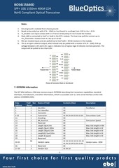
Notes:
1.
2.
3.
4.
Circuit ground is isolated from chassis ground.
Needs to be pulled up with 4.7k – 10kΩ on host board to a voltage from 2.0V to Vcc + 0.3V.
Tx_Disable is an input contact with a 4.7 kΩ to 10 kΩ pullup to VccT inside the module.
Mod_ABS is connected to VeeT or VeeR in the SFP+ module. The host may pull this contact up to
Vcc_Host with a resistor from 4.7 kΩ up to 10 kΩ.
5. RS1 are module inputs and are pulled low to VeeT with > 30 kΩ resistors in the module.
6. This is an open collector output, which should only be pulled with a resistor of 4.7k - 10kΩ. Pull up
voltage between 2.0V and 3.6V. Logic 1 indicates loss of signal; logic 0 indicates normal operation. The
output will be pulled to less than 0.8V.
Pinout of Connector Block on Host Board
7. EEPROM Information
The SFP MSA defines a 256-byte memory map in EEPROM describing the transceivers capabilities, standard
interfaces, manufacturer, and other information, which is accessible over a 2 wire serial interface at the 8-bit
address 1010000X (A0h).
Data
Address
0
1
2
3-10
11
12
13
14
15
16
17
18
29
30-35
36
37-39
Field Size
(Bytes)
1
1
1
8
1
1
1
1
1
1
1
1
Name of Field
Contents (Hex)
Description
Identifier
Ext. Identifier
Connector
Transceiver
Encoding
BR, Nominal
Reserved
Length (9μm) km
Length (9μm) 100m
Length (50μm) 10m
Length(62.5μm)10m
Length (Copper)
XX
XX
XX
XX XX XX XX XX XX XX XX
XX
XX
00
XX
XX
XX
XX
XX
00
XX XX XX XX XX XX XX XX
XX XX XX XX XX XX XX XX
00
XX XX XX
Formfactor
1
16
Reserved
1
3
Reserved
Vendor OUI
Vendor name
-5-
Transmittter Code
Transceiver Speed
Max. link length in KM
Max. link length in M
Max. link length in M
Max. link length in M
Max. link length in M
Vendor name - OEM
�
BO54J15640D
SFP+ 10G 1550nm 40KM CDR
RoHS Compliant Optical Transceiver
40-55
16
XX XX XX XX XX XX XX XX
XX XX XX XX XX XX XX XX
XX XX XX XX
XX XX
Vendor PN
56-59
60-61
4
2
Vendor rev
Wavelength
62
63
1
1
Reserved
64-65
66
67
68-83
2
1
1
16
Options
BR, max
BR, min
84-91
92
93
94
95
8
1
1
1
1
Vendor date code
Diagnostic type
Enhanced option
SFF-8472
96-255
160
00
XX
CC BASE
XX XX
XX
XX
XX XX XX XX XX XX XX XX
XX XX XX XX XX XX XX XX
XX XX XX XX XX XX 20 20
XX
XX
XX
XX
Vendor SN
CC_EXT
Product Number depending on Part
Vendor revision
Transceiver
Wavelength
Checksum of bytes 062
Part serial number
Year, Month, Day
Diagnostics
Diagnostics
Diagnostics
Checksum of bytes 6494
Vendor Specific
8. Digital Diagnostics / Digital Optical Monitoring
The transceiver provides serial ID memory contents and diagnostic information about the present
operating conditions by the 2-wire serial interface (SCL, SDA).
The diagnostic information with internal calibration or external calibration are all implemented,
including received power monitoring, transmitted power monitoring, bias current monitoring, supply
voltage monitoring and temperature monitoring.
9. Recommended Interface Circuit
-6-
�
BO54J15640D
SFP+ 10G 1550nm 40KM CDR
RoHS Compliant Optical Transceiver
10. Mechanical Specifications (Unit: mm)
Contact Information
CBO GmbH
Friedhofstraße 25
45478 Mülheim an der Ruhr
Germany
Tel.:
Fax.:
eMail:
web:
0049 – 208 – 777 247 - 0
0049 – 208 – 777 247 - 99
info@cbo-it.de
www.cbo-it.de
-7-
�
 Historical archive . public document