Publ. No.
Aabenraavej 13-17, DK - 6340 Krusaa, Denmark
Tel: +45 74 62 20 88
Fax +45 74 62 74 07
E-mail: bukh@bukh.dk – Internet: www.bukh.dk
Vorkshop Manual
for
BUKH sail drive
TYPE Z-7
009W2S20-R01
009W2S20
�
S2
CONTENTS
Oil change and gear ratio .......................................................... page S 3
Zinc anode................................................................................. page S 3
Outside maintenance ................................................................ page S 3
Removal of sail drive from engine and boat .............................. page S 3
Alarm function of double membrane .......................................... page S 5
General (for assembly and dismantling of sail drive) ................. page S 6
Assembling procedure for sail drive .......................................... page S 7
Intermediate housing and intermediate shaft (drawing) ............. page S 12
009W2329-R01
�
S3
Oil Change and Gear Ratio
As an alternative to the BW7 gear the DV36 can be equipped with a sail drive.
The reduction ratio is 2.25:1 for “AHEAD” and 2.25:1 for “REVERSE”.
The sail drive will need no other attendance than regular change of oil. This to be carried out after
the first 25 hours of operation and then every 150 hours or once a year.
Carry out the oil change when the boat is on land by loosening the drain screw in the bottom of the
sail drive enabling the oil to run out.
Refill with fresh oil through the filler hole at the top of the sail drive to a quantity of 3.3 litres
corresponding to the upper mark on the dip stick.
Use the same quality of oil as for the BW7 gear.
Zinc Anode
A replaceable zinc anode is fitted at the propeller. Check this anode twice a year or as required all
depending on the waters you are sailing in.
Outside Maintenance
Do not grind thoroughly when careening the boat. Damage to the surface treatment should be
treated as soon as possible with special BUKH paint.
The sail drive should be coated with the same bottom paint as the rest of the bottom of the boat.
Removal of Sail Drive from Engine and Boat
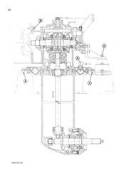
(see drawing page S4)
1.
2.
3.
4.
5.
Beach the boat.
Loosen the bolts marked A in the flange at the double membrane.
Loosen the bolts marked B on the flange towards the engine.
Loosen the sensing element marked D for water in the double membrane.
Lift the sail drive clear of the foundation.
It may be necessary in point 2 to loosen the engine mountings from the foundation and to lift the
engine a little in order to loosen all the bolts marked B.
009W2329-R01
�
S4
009W2329-R01
�
S5
‘
Alarm Function of Double Membrane
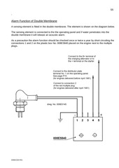
A sensing element is fitted in the double membrane. The element is shown on the diagram below.
The sensing element is connected to the the operating panel and if water penetrates into the
double membrane it will release an acoustic alarm.
As a precaution the alarm function should be checked once or twice a year by short-circuiting the
connections 1 and 2 on the plastic box No. 008E5840 placed on the engine next to the multiple
plugs.
009W2329-R01
�
S6
The instruction below is stated for assembling of sail drives as broadly the disassembly
procedure is to be carried out in reverse order noting the thickness and the placing of the
different intermediate washers.
General
At the assembly all parts must be clear, burred and free from grease.
In order to prevent wrong measuring when adjusting, the parts should normally not be oiled when
being assembled.
Heat the mounting houses with a hot-air blower, an oven or the like to 80°C when fitting the
bearings in accordance with the procedure. However, the temperature must not exceed 140°C.
When replacing gear-wheels, change them two and two, i.e. do not change one single gear-wheel,
but one connected set of gear-wheels.
When replacing the coupling arrangement at the top of the sail drive, replace the whole
arrangement without repairs of single components of it. This should be seen in the light of the fact
that a correct repair of the coupling arrangement demands a very advanced measuring equipment
which only very few have at their disposal.
The special tools mentioned in this instruction are not numbered, but can be ordered with
reference to this section of the workshop manual through BUKH´s spare parts department.
Both distance measure and flange clearance are always marked on the wheels, and they apply to
the wheel on which they are written.
The sail drive comprises 11 filling pieces each consisting of an intermediate washer at the least.
009W2329-R01
�
S7
Assembling Procedure for Sail Drive
1.
Measure the intermediate piece (between engine and clutch housing), the clutch housing
and the end cover for the same, and then the “K” measure can be worked out.
2.
Up-end the clutch shaft so that any clearance is equalized. (about 2 kg compression, if it is
not possible to up-end the shaft). At the same time the gear-wheel should be engaged.
Measure the “J” measure now. Measure the “C” measure for use later on under point 10.
3.
Measure the “H” measure in order to find the centre of the vertical intermediate shaft.
Measure the “G” measure as “F” measure + “A” measure, as the “A” measure is written on
the gear-wheel.
Measure the “F” measure while the shaft still stands on its edge, so that any clearance is
equalized.
Calculate the thickness of the intermediate washer “IIv” as: “H” measure minus “G” measure.
4.
Calculate the thickness of the intermediate washer “IIr” as: “K” measure minus sum of “J”
measure and intermediate washer “IIv”.
5.
Fit the intermediate piece on the clutch housing with liquid jointing as filling piece.
6.
Fit the reversing part at the top of the clutch housing as follows:
a.
Put the reversing lever in “Neutral” position and the pipe collar too.
b.
Lead the reversing house with gasket into the opening of the clutch housing and press the
shifting eccentric into the wedge-shaped groove of the shifting fork. In order to equalize the
axial clearance between the shifting fork and the pipe collar the shifting eccentric should be
fitted with the groove in the shifting fork with a light pressure.
c.
Tighten the reversing house in this position.
NOTE: The clearance of the angle between the longitudinal shaft of the gear and the
one of the reversing lever must be observed. The angle is to be 90°±30`.
Use a reference gauge for this purpose.
When adjusting the reversing house the fixing screws must not encounter the wall of the
slots of the reversing house as this would lead to wrong adjustment.
d.
Shift the reversing lever in both directions and test the shifting function. In both shifting
positions the pipe collar be connected (click), when the angles of engagement measured
on the reversing lever are as equal as possible.
Besides, it must always be possible to turn the reversing lever 37°. The adjustment is
corrected by axial displacement of the reversing house, the angle of 90° being observed.
e.
In order to test the function of both clutches turn the input shaft (clutch shaft) round by hand
and brake the output shaft by hand when engaged.
The upper part of the sail drive is now temporarily ready.
009W2329-R01
�
S8
Measure on the intermediate wheel as follows:
7.
1.0 mm is chosen as thickness of the intermediate washer “III” as starting point.
8.
Freeze the gear-wheel and measure the stagger between the inner collar and outer collar
of the bearing. Fit the bearing with the ball filler hole facing the adjusting washer “IV”.
Fit the next bearing correspondingly. Punch the inner collar when fitting it to secure that
the two inner collars touch each other.
Measure the intermediate bearing housing for the measures “D” and “E”.
9.
Measure the “M” measure for use later on.
10. Calculate the thichness of the intermediate washer “IV” now, the intermediate washer = “C”
measure minus the sum of “D” measure and “B” measure.
“B” measure is written on the gear-wheel.
11.
Measure the “L” measure, then calculate the thickness of the intermediate washer “V”,
this washer being = “L” measure minus the sum of “E” measure and the intermediate
washer “IV”.
12. Fit the intermediate wheel in the bearings and secure it with a Seeger circlip in accordance
with the drawing for it.
13. Fit the bearing housing with intermediate wheel in the gearbox with O-rings.
14. Remove the end cover in the clutch housing together with the shifting fork arrangement for
the test described in the next point (15) to be carried out.
15. Mount the clamping tools for fixing of the big gear-wheel. Mount a dial indicator on the gearwheel of the clutch shaft through the upper opening at the reversing handle of the clutch
housing, so that the indicator meets the following requirements.
a. Point of contact about in the middle of the tooth flank and of the pitch circle.
b. The indicator should be vertical in the longitudinal and height direction of the tooth flank.
With the bigger gear-wheel (z=45) fastened, measure the flank clearance. Measure both
the wheels of the clutch shaft in this way.
If occasion should arise, adjust the clearance to the one stamped which is correct by
changing the washers “IV” and “V”.
16. Refit the end cover and the reversing arrangement as stated under point 6.
17. Measure the propeller house for “O” measure, “W” measure and “U” measure.
18. Fit the bottom conical gear-wheel marked “X” at a torque of 125 Nm±5 Nm (13 ±0.5 Kpm)
on the intermediate shaft of the propeller house.
19. The intermediate washer “VI” normally is 1.5 mm and must never be used smaller. Fit the
intermediate washer “VI” on the shaft together with the bearing, the ball filling opening of
which should turn up.
20. Measure the intermediate washer “VII” with a feeler gauge and fit the correct thickness
together with the upper locking ring.
009W2329-R01
�
S9
21. Calculate the “T” measure. The “S” measure is stamped on the gear-wheel whereas the
“R” measure has to measure. “T” measure = “S” measure minus “R” measure.
22. The intermediate washer ”VIIIB” should be: the sum of “T” measure and “Q” measure
minus the difference of “U” measure and “O” measure.
23. Find the thickness of the intermediate washer “VIIIA” by measuring the bearing outer collar
“N” measure, after which the washer should be: the sum of “M” measure and “O” measure
minus the sum of intermediate washer “VIIIB” and “N” measure.
24. Having finished the measuring of the intermediate shaft remove the gear-wheel marked
“X” again and fit the needle bearings “Z” and “Y” after the house has been heated.
25. Fit the intermediate shaft with bearings in the propeller housing.
26. Refit the gear-wheel marked “X” and tighten it with the same torque as indicated in point
18.
27. Check whether the distance measures of the small gear-wheel are correctly adjusted with
the fitted washers (“T” measure) with special tools.
28. Measure the “V” measure.
29. Heat the bearing housing “Æ” and fit the bearing with the ball filling opening facing the
gear-wheel side.
30. Measure the thickness of the washer “X” with a feeler gauge (between locking ring and
outer collar of the bearing ).
31. Calculate the intermediate washer “IX”. The “W1” measure is indicated on the gear-wheel.
The intermediate washer = “W” measure minus the sum of “V” measure and “W1” measure.
32. Fit the output shaft with gear-wheel in the cover for propeller house with seals.
33. Fit cover with shaft and gear-wheel in the propeller housing.
34. Check the flank clearance at the output shaft.
The intermediate shaft is blocked and on the propeller shaft a lever is placed, on which
should be measured at difference radius R=40 mm. The shaft nut must be tightened.
The correct flank clearance is indicated on the gear-wheel and is corrected at the
intermediate washer “IX” if necessary.
On pages S10, S11, S12 and S13 longitudinal sections of the sail drive with places of measuring
drawn in are shown, partly by a general drawing and partly by detail drawings.
009W2329-R01
�
S10
009W2329-R01
�
S11
009W2329-R01
�
S12
009W2329-R01
�
S13
009W2329-R01
�
 Historical archive . public document