https://ntrs.nasa.gov/search.jsp?R=19810013543 2020-07-03T17:38:49+00:00Z
NOTICE
THIS DOCUMENT HAS BEEN REPRODUCED FROM
MICROFICHE. ALTHOUGH IT IS RECOGNIZED THAT
CERTAIN PORTIONS ARE ILLEGIBLE, IT IS BEING RELEASED
IN THE INTEREST OF MAKING AVAILABLE AS MUCH
INFORMATION AS POSSIBLE
�
NASA TECHNICAL MEMORANDUM
"SOLARIS"
"I'- w-1 I-, FOR OUTEL SPACE RENDEZVOUS AND OPERATIONS
ORBITAL foTRNIUN - Awww-0- 1,
j. j. Funavot
V
Translation of "Solaris: Station orbitale- Laboratoire Automatique pour
le Rendezvous et les Interventions Spatiales", Centre National D'Etudes
Spatiales, Centre Spatiale de Toulouse, Toulouse, France, Report, September 10, 1980,
pp, 1-27
(NASA-TM-76403) SOLARIS.-
011BITAL STAI^10NAU TOMATIC AIJABORATORY F-ANUS 4Z
aV
73
Ch
CUT
LIi J-PACE
RENDEZVOUS AN D
OVERATIU0S
(Natiouai
Aeronautics ad SPdce Admillistratir),n ) j I
HC AJ3/MF A01
unclds
CSCL 22B G3/15 414'142
01
IN
.
NATIONAL AERONAUTICS AND SPACE ADMINISTRATION
APRIL 1981
WASHINGTON, D.C. 2054 6
�
I
t
.
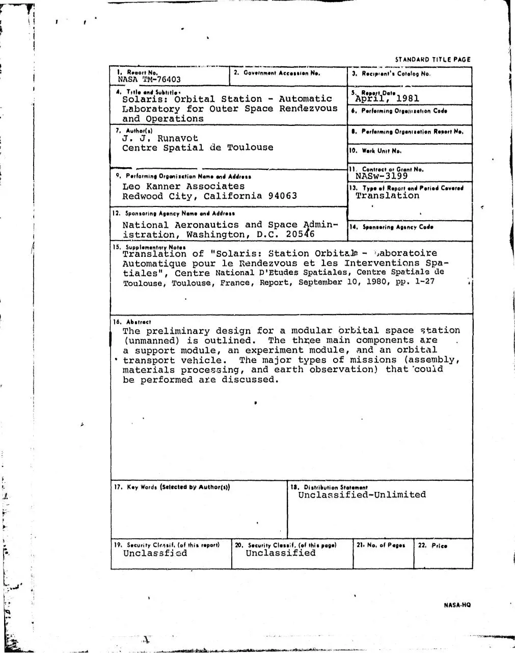
STANDARD TITLE PAGE
1. Report No.
TGovernment Aleeeelen N•.
NASA TM-76403
A. Toile and Subtitl• .
Solaris: orbital Station - Automatic
Laboratory for Outer Space Rendezvous
and Operations
7. Authors)
J. J.
3, Recipients Catalog No.
S. Repoli Dots
April, 1981
6, Performing Drg•i""setion Code
S. P•rfatmine Ofgonls•tion R•pOrt No.
Runavot
Centre Spatial ire Toulouse
10. work unit No.
11. Contract at Grant No.
NASw- 3199
4. Performing Drgoniection Nem• end Address
Leo Kanner Associates
Redwood City, California 94063
13 Type of Report end Period Coveted
Translation
12. Sponsoring Agency Name and Address
National Aeronautics and Space. Admin is tration, Washingto n, D.C. 205Q6
nestin g Agoney Code
ffp..
IS. Supplementer Notes
Translati
on of t"Sol.aris: Station Orbita10 - =oaboratoire
Automatique pour le Rendezvous et les Interventions Spatiales"', Centre National p ' Etudes Spatiales, Centre Spatiale ate
Toulouse, Toulouse, France, Report, September 10, 1980, pp. 1-27
16. Abstract
The preliminary design for a modular brbital space Station
(unmanned) is outlined. The th4ee main components are
a support module, an experiment module, and an orbital
• transport vehicle. The major types of missions (assembly,
materials procering, and earth observation) that'coud
be performed ale discussed.
17. Key Words (Selected by Author(s))
1s. Distribution Statement
Unclassified-Unlimited
19. Security Clrrisif. (of this report)
Unclassfi cd
20. Security Cless'sf, (of this page)
Unclassified
21. No. of Paget
22. :Price
NASA-NO
�
^
e
TABLE OF CONTENTS
I. Introduction
XI, Future Needs and New Capabilites; The Response Embodied in
Project Solaris
III. Principal Missions
IV Description of Project Souris
V. Development
rA
�
r
"SOLARIS"
ORBITAL STP,TION - AUTOMATIC LABORATORY
FOR OUTER SPACE RENDEZVOUS AND OPERATIONS
J. J. Runavot
Centre Spatial de Toulouse, Toulouse
I. Introduction
Solaris is made up
of three
or useable as the need arises:
:Hain components,
either permanent
- The orbital station, placed in a 780 I= heliosynchronous
orbit, 6 AM - 6 PM local time, will constitute a true si ort
module during its fifteen years of operation. It will be useable
in various applications: earth observation, synthesis of material,
and outer space construction. The services it will provide
are either completely new for Europe, such as rendezvous and
docking, or represent a change in scaler e.g., the power
supplied to payloads or modules connected to the station
(10 kw at the end of its life) and the communications
capabilities provided (continuous transmission of hundreds
of 24bfsec in real time through the use of geostationary
relays).
- An operations module with advanced remote manipulation facilities. It thus will be able to carry out complicated tasks
dealing either with materials synthesis experiments or
assembly and construction.
'.
The module, carried up by a space vehicle, can be
connected to the orbital station. When remaining locked
onto the space vehicle, it prefigures a complete operations
system that would eventually be able to operate in geostationary orbit, for example.
*Numbers
in margin
indicate pagination in the foreign
text.
1
LL
�
Orbital transport modules (automaticA space vehicles) will make
possible the continued operation of the system thus put in
place; Tens of rendezvous could be accomplished during the
orbital station's li.fespan. Through such rendezvous, the
nature of missions and of the operations module will be altered.
Aside from the maneuver and rendezvous function, the vehicle
offers the possibility of making recoveries, either in separate
pieces sent back over a period of time or by tha return of a
large reentry vehicle containing a two-ton payload.
Solar is makes it possible to develop these new capabilities,
notably rendezvous, recovery, and control. They are indispensable if one hopes to be a power in the uses of outer space.
Until now the ability of a nation to maintain its independence in sapce technology revolved around one essential
the possesion of a launcher capable of placing
point
objects in geostationary orbit.
In the next ten years, the key to independence will be
skill in controlling complex processes in orbit, putting
into operation (if not constructing) large paltforms, repairing
space vehicles without interrupting service, etc.
Project Sol.aris will permit the unification of European
efforts in the area of technical development with the objective of mastering such operational techniques.
This document presents a, possible,, albeit preliminary, design
of the orbital operations system. It is based on using the Ariane
TV launcher and ret. ults from reflection on the future of outer space,
the new capabilities that must be developed, and the possibility Project Solaris offers Europe and France to take up the challenge through
a major but reasonable effort.
/4
Chapter 1T summarizes the new capabilities, presents the
2
$
y
�
response embodied in Project Solaris, and compares it to the competing
American and Russian systems.
A
Chapters III gives an account of possible
Solaris.
missions and uses for
Chapter IV presents the basic design and general characteristics
of the system. From amongst the possible solutions, it identifies
existing technologies and those which demand a
R and D effort. This effort in itself constitutes one
of the justifications for undertaking Solaris's development, which
both unifies the work and demonstrates the acquired /apabiliti,es
those involving
considerable
in
orbit.
Lastly, the development of Solaris is sketched out in Chapter V.
Particular attention is paid to the way it overlaps with the R and
D program.
II. suture Needs and New Capabil. ties: The Response Embodied in
Proj ect Solaris
,/5
.II.1. Future Nee ds and New Capabil it i es
The response to what is
at stake in outer space during the
next twenty years necessitates the use of the most effective technology
to carry out space operations. To do this it is necessary
- to dispose of lauch equipment which lowers the cost per
kilogram in orbit;
- to be able to get around the limits in mass and dimensions
inherent in this equipment, to alter or further develop the
space system;
- to increase the operational life of space systems;
to
exchange material
with the
system in
orbit (deposits and
3
.
I
�
{
withdrawals);
- to dispose of larger on board electrical power supplies;
- to have reliable, practically permanent, high speed communications linkages with the systems in orbit or between systems.
11.2_.
The Response Embodied in Project Solaris
Project Solaris, "using the Ariane IV launcher, attempts to
respond to all the preceding con lOerations. It can be broken down
into three parts;
An orbital station whose primary function is to be a
poiier supply module furnishing on the order of 10 kw of useable
power, and also featuring:
- a structure
for receiving "payloads".-
- the ability to rendezvous with automatic space
vehicles and to grow through a succession of dockings;
a song lifespan (15 years);
- an alterable, modular design for all the subsystems
required by the preceding functions;
- a very rapid data transmission capability.
An operations module, an extension of the station for
performing complicated mechanical tasks and including:
- advanced computer circuitry;
y
t
remote manipulator arms;
i
f ^
IY
-
4
a surveillance system including television cameras.
/6
�
I
j
Automatic vehicles, launched as needed and designed to offs-^r,
besides facilities for navigation and rondezvous, equipment
to recover a ballistic reentry vehicle as well as maximum
possible payload size and mass.
This strategy is based on using a low orbit instrument, as is
consistent with the evolution of technology. It paves the way
for other missions, notably those in geostationary orbit.
It i; interesting to compare the overall characteristics of' th is
instrument with those of other systems, whether existing (Salyut
Progress) or under development (Power 'Rodule).
C omparison,with the Power Mod ule
NASA's Power Module will complete the Space Shuttle system by
supporting .several. Space Shuttle missions during its 5 year life r an.
It can function in two modes:
connected to the Space Shuttle (in its Spacelab configuration,
for example) to provide it with extra heat exchange capacity
and 25 kw more power;
- in "free flight", but then the payload that becomes attached
to it to obtain power, stabilization, and heat dissipation will
have to carry its own communications system.
The comparison is "limited to the orbital station and the Power
Module:
4
5
^
.r
�
1986
Launch Date
Orbit
Mass
380 km, 55 0 or 28.5 0
1990
780 km
(imposed by the Shuttle) heliosynchronous
14,000 kg
4,100 kg
(1100 kg pyld)
Power Supply.
Solar Generator Area
533 m2
160 m2 (As,Ga)
Orientation Mechanism
turning
fixed
Batteries
4923 kg
120 kg (NiH2)
25 kw
Continuous Power
rurnished Payload
10 kw aft 15 y
20 kw at start
Heat Dissipation
Extendable Radiators
rreon Loop
Dissipation Capacity
2000
at Teq
Telecommuni cations
2 (350 kg)
no
yes
no
15 kw
8-10 kv'•
dependent on
up to 600 Mb/s
ti100
111
/8
comparison with the Salyut-Progress Sysl,em
This system, presently operated by the Soviet Union, is designed
for manned flights. Comparison with it is made only in capabilities
other than life support:
Progress
OTM
4900 kg
Mass at Liftoff
7000 kg
Useable Volume
6.6 m 349
Payload Mass
2300 kg
4000 kg
Autonomy
3 days
7 days
Attached to Station
30 days
several, months
6
m3
�
350 km 51.6*
780 km
heliosynchronous
Mass at Liftoff
18,900 kg
4100 kg
Useable Volume
100 m3
(w.1th crew)
Orbit
4 kw for whole unit
probably 1.5-2 kw
for payload
Power
Commuoications
a fey, Mb/s
for limited
_periods
8 m3 (internal)
possible extension
up to 140 m3 (external)
10 kw for payload
up to 600 Mb/s
permanent
10
III. Princi2al Missions
Through its goals, its design, and the technology it puts to work,
So?ar:ls opens up a vast field of applications, as illustrated by its
three principal missions:
- Experimentation with assembly and construction in orbit, which,
beyond the services offered by the station, brings into play
the operations module and its refined remote manipulation capabilities. It constitutes the ;first stage in developing a
workshop for constructing and assembling large structures in
space.
Synthesis of materials in space. This is the last stage before
actual production. The processes involved are ones whose promise
and preliminary specification will have been established at
the end of a program of study and experimentation in this
area (theoretical studies, experiments on the ground, flights
of short duration). For this mission, the high power supply,
the capacity for orbital operations, and the recovery feature
7
�
a
Il
3..
Y
5
^
^
r
n
E
aw
e
r
^
^r
I^rr'
„
'k A
y}^^
iIT
�
4
will allow the processes to be perfected
or a pilot production
run to be carried out.
An earth. observation mission for which the high power and
high speed transmission capabilities make the use of microwaves possible.
111.1. Construction in Seace
if an immediate jump to very Large space
platforms is not made,
the construction of large beams would appear to be an obligatory* step.
Associated with rendezvous and assembly, it paves the way for a whole
series of new applications:
- in observation and location (passive radiometers, interferometers);
- in the creation of large scientific interferometers or
telesc ope► z
-- etc.
Solaris represents a first step down this road, even if its
dimensional objectives are modest. It is in effect a test bench
for materials, procedures, and construction methods thanks to its
remote manipulator arms. It also tests out the assembly and com-
bining of deformable structures ("impactless" docking). it could,
for example, put together beams tens of meters long for constructing
an interferontetric station.
Creating such a station would require two flights of the auto-
matic space vehicle: The first would carry three containers (with
individual dimensions of 1.5 m x 1.5 m x 1.5 m). Each container
would provide the material for constructing, through remote manipulation, a beam thirty meters long with a deployable antenna at its
end. The second flight would carry the cental body on which the
three branches of the star would be assembled.
9
�
1
t%'ONSTRUCTION n CUTR n .
Constructing Beam 1
4 al I
-RUCT-CH P OUTRE 2 Constructing Beam 2
S TIOCKAGE O CUTRE :
}^
}^
Storing Beam 1
�
3
ASSEMBLAGE PGUTRES CORP S
9
Assembling Beam & Body
-f v `°-A
R
/f v r
1y^
^
-
DtPLOIEMEN"
Deployment
i
k
1
'
�
e
111.2. Synthesis of Materials in Space.
The greatly reduced gravity obtainable on board sk-.Ace venicies
makes it possible to put into operation processes of preparation
or separation that work better than on the ground, or are even
impossible there:
- contactless transformations for products which react with
crucibles (glasses, ceramics, alloys);
production of products of high crystalographic quality from
liquids or gases (pure, massive crystals, new alloys);
- separation and purification of products with the aid of
forces whose amplitude is much weaker than gravity on the
ground (vaccines, pharmaceutical products).
The products and processes amenable to space operations will
be identified in the years to come, at the end of a program of
fundamental research and of experiments of limited duration or
similarity.
The final
perfection of selected processes or a pilot production
run requires:
-
a residual gravity of less than 10 -5 g;
- several kw of electric power;
the ability to dissipate the same amount of power in the
form of heat;
- the possibility of recovering finished products, in moderate
or large quantity, and possibly certain production materials
as well;
extensive capacity for automating processes and for more
or less autonomous mechanical. operations.
12
�
Solaris makes this group of features available. It supports
rigorous and multiform experimentation and an annual production of
several hundred kg for processes able to last several months:
19
i
-5
a residual gravity far lower than 10
g (faxed solar generator, weak primary structural member, relatively high
altitude orbit);
10 kw of available electrical power at the end of lifespan
(20 kw at the beginning);
-
large
cold surface for dissipating
heat;
- recovery with the aid of reentry vehicles delivered by orbital
transport vehicles, either of two tons in a single shipment
or of several hundreds of kg divided up over time;
- Capacity for automation, either entirely within the payload
itself or aided by the station's computer, and for mechanical
operations aided either by the station's remote manipulator
arms or by the operations module.
lrl.3. Earth Observation
Through the support se:vices it offers, Project Solaris permits
the execution of earth observation missions difficult to envisage with
conventional space vehicles:
- large amount of available electric power in the station
for instruments;
- large area for attaching instruments on the side of the
station facing the earth, excellent heat dissipation facilities,
and the availability of remote manipulation systems for
assisting deployments or other tasks;
Capacity for high speed, continuous data transmission in
13
�
r
r
7
real time.
These earth observation missions are based on the use of passive
microwave radiometers, and especially of synthetic aperature radar of
either high resolution (metrical) or high informational quality
(mul.tifrequency or multi,polarity) .
As an example, the orbital station could receive and support
one of the following two instruments;
10 BHz High Resolution Synthetic Ape:ature Radar
- Resolution
- Scanning Width
2 m
25 km
- Antenna
4 m x 1.25 m
- Electrical Power Transmitted
4 kw
- Electrical Power Absorbed
10 kw
- Thermal Power Dissipated
6 kw
- Telemetric Output
360 Mb/sec
5 and 10 BHz Thematic Synthetic Aperature Radar
- Resolution
Scanning Width
- 2 Frequencies and 2 Polarities
(2 Transmitters)
- 4 Antennae 10 m Long
- Transmitted Power
'
- Electrical Power Absorbed
Thermal Power Dissipated
Telemetric Output
(after on board
holographic processing)
i
iF
14
r
0V
10 m
100 km
10 BHz VV and VH
5 BHz VV and VH
.4 m wide (2)
.8 m wide (2)
600 w per transmitter
3 kw + 2.5 kw (processing)
ti3 kw
300-400 Mb/sec
Lz 5
n.
�
i
a
.
The station's lifespan, its range of possible activities, and the
capacity td. carry up new instruments in automatic space vehicles make
continuous, evolving missions foreseeable.
Z6
IV. Description of Solaris
A preliminary, but indicative design for t'.),e system has been
proposed. it is conservative in certain aspects, notably concerning
the orbital station's general architecture, However, it has the
advantage of showing that the system's assigned objectives can be met
with the Ariane IV launcher, given technological developments that
will in any case be necessary in the future. Also included are
new, adapted designs for a certain number of subsystems.
IV.1. General Characteristics
The system is put in place in several steps. The first is the
launching of the orbital station. The orbit decided on is a circular heliosynchronous one with an altitude of 780 km and an ascending
node at 6:00 PM local, time. This has the following advantages:
- best station configuration (energy generation and storage, heat
dissipation, etc.);
- less acceleration and residual vibration (fixed solar generator
parallel to the direction of motion);
- capacity for observation missions with global coverage;
- accessibilty of recovery site.
The price is a loss in mass of several hundred kilograms and
a longer time required for rendezvous and recoveries. This ill without
great importance for an automatic system carrying only production
materials.
Similarly, the atmospheric reentry under consideration is of
15
�
• b;tllistic type, the easiest to master at first. At the cost of
• greater rate of deceleration (but perfectly compatible with the
materials to be recovered), it offers the maximum payload volume and
an excellent targeting precision (about la x 20 km).
Lastly, the docking method chosen is of minimum impact. A system
of this kind must include high performance optical terminal guidance
equipment. It is compatible with the minimum thrust deliverable by the
means of propulsion on the automatic vehicle. Such a system guarantees
that the station's solar generator will not jar loose during docking
and is obligatory for future docking operations involving large
structures.
TV.2. The Orbital Station
The orbital station receives and supports the functioning of
payloads for the missions indicatied above.
It consequently performs the following main functions:
- Generation and storage of energy: It is able to continuously
furnish payloads with 10 kw of power.
- maintenance and modification of orbit: It maintains the specified heliosynchronous orbit and is capable in the course of
its life of making ten excursions to neighboring heliosynchronous orbits (variation in semi -major axis on the order
of 25 km) .
- Control of attitude: It provides attitude control compatible
with the various missions. In particular, it should permit
angular velocities of less than a few 10 -4 degrees/sec and
linear accelerations of less than 10 -5 g.
- Data transmission: Through the intermediary of geostationary
relays, the station can continuously transmit data in real
time at very high rates (200-600 Mb/sec, according to the
36
/17
�
^
`
~
17
U^
�
R
^
i
option chosen.
it in addition performs less conventional functions representing
a real advance in European space know-how:
- docking of automatic spce vehicles;
- reception of variable payloads which can be added to by successive dockings.
A preliminary calculation of mass indicates that the station
could be put into the specified orbit by the Ariane IV launcher with
a comfortable margin, even at the present stage of design.
In contrast, the desired performance and lifespan, and the ability
to grow and change configuration, necessitate& new designs (for
example,. compromises between super-redundance and repair by interchangeability) for the majority of subsystems. New equipment and
techniques have to be developed.
- On Board Energy Subsystem
To obtain the desired power capacity and lifespan, highl y
efficient cells (AsGa, for example) must be used so as to reduce the
size of the solar generator, which nevertheless will'. require the
development of a new'design.
As far as energy storage and distribution in the station are
concerned, a new architecture will have to looked into and developed
(even if continuous distribution is retained). It will have to
be adapted to modularity, variable loader serviceability, and a
high level of power.
As a corollary, high voltage distribution channels, various
associated components, regulating limiters (by cutting out, for
example), and batteries of high power ger unit mass (NH, etc.) have
to be developed. Finally the advantages of kinetic storage and dis4
18
/19
�
a
.
tribution by a lternating current should be the object of studies to
determine alternative solutions to the basic problem.
- Th ermal Subsyst em
As a result of the long lifespan, the variability in operating
conditions, and changes in configuration, it has to be modular and
entirely, active. All its components should boi developed in conformity
with the principle of control by on board computer.
- Attitude and Orbital Control Subsystem
Besides a new architecture adapted to changes in configuration,
the station's relative flexibility, and numerous functional modes,
certain innovations will Probably be necessary in the equipment
(gyrolaser, ionic p,:opuls .on with greater thrust) .
- On Board Command and Data Transmission Subsystem
The necessary developments concern;
- High speed communication with the relays (transmitter,
automatic tracking antenna) and with the interior of the
station (optical fibers or diffused infa-red linkages);
- Architecture and standard data channels adapted to changing
station configuration, reversible connections, and rapid
two-way exchanges;
- Reliable reversible connection technology;
- High performance hybrid components;
Rendezvous, Docking
Besides two-way connection technology, it is necessary to
19
�
r
c
r
r
I
► a
I
r
1
^
r
r
F
i
1
i
^ rr^uY.im^ ..
Orbital Stat n at Liftoff
20
•
-
^n.
STATION C'RSI ALE AU LANCE.mmvNT
uK
rsr.: xAr;+vre.^e7+ewc_.....s^^
.-,..e.w _^._
--
-
�
develop a relatively long-range traj ectory calculation system for
two objects in orbit, and especially on the basic elements for terminal;
guidance (based, for example, on lidars) and docking mechanisms.
21
Iu.3. The Aerations Module
The module will represent the concrete result of an ambitious
R and p program in the fields of automation and remote manipulation.
Tha basis of the program will be existing French expertise, as brought
together in a research association (with they participation of CEA,
Renault, etc.).
The OM's job is two-fold: Within the narrow framework of Solaris,
i. e., docked to the orbital station., it w ill perform the complicated
mechanical operations needed for certain experiments (ovens, deployment
of appendages, assemblies, etc.). Elsewhere, carried by the transport
module in autonomous orbit, it will constitute a prototype system for
servicing satellites or large structures in spaces
In the second case, all that is required is an extension of
the transport module's energy generation and communications capabilities.
In the first case, it will use the maximum capacity of the transport
module and permit successive dockings, which will extend and enlarge
the orbital station.
- Architecture
The module is basically made up of:
- two docking interfaces, male and female;
- a central compartment which can contain complicated materials
processing experiments, among other things;
a . group of remote manipulator arms, tan meters in length, to .
which grasping mechanisms, specialized tools, and sensors can
21
�
w
^
Vrt
I ^F""
i
ro^
r
F
i
f
1
^
4
s
^'
4
4
1 ^
1
Y
a
i 0.0 13'
i
r
two
^
a
t
kgg
^
I
t
x
4
I
AT
i
t T
A Y
3
^
IIOD JLE
7 IC N
D i =ERti'=
At! LANCEMET3"..'
operations Module at Liftoff
-
22
�
be fitted. The arms can range over fairly great distances
outside the module or perform work inside the cental compartonent.
- computer circuitry with advanced software able to control: the
maipulator system in either sequential or closed loop modes,
- Subs stems and Technical Developments
The needed technical developments essentially concern the manipulator arms and the computer circuitry.
Firstly, all the manipulator arm components, articulations,
motors, and sensory and grasping gear, must be developed and chocked
out.
Secondly, besides perfecting the computer software, a highperformance computer interfaced with the one in the orbital station
has to be created.
,A certain number of the other required innovations are the same
as for the orbital station, particularly concerning two-way connection
technology.
Lastly, system-wide studies should take place parallel with the
rest of the program on the sub`ectsof repairability and assembly and
construction methods in s ace.
IV A . The Automatic Space Vehicle
23
The automatic space vehicle has the following functions:
transporting modules toward the station (for maintaining
and altering it), including in particular the reentry vehicle
and operating module;
injecting the reentry veni.cle or material destined for destruction into the atmosphere with the proper speed and
attitude.
23
�
*
i
.
It must therefore be capable of making all the corrections
necessary for rendezvous and reentry, of approaching and docking
with the station and of remaining t%adhanically and eletrically
linked to it for a few days.
As an extra function, the space vehicle's propulsion and navigation module can also be used to place objects in geostationary
orbit after minor adjustments have been made to it.
- ,Architecture
Two factors have been decisive in the automatic space vehicle's
design, They are thu need for the maneuverability and autonomy inherent
iq an automatic systen, and the desire to obtain the maximum possible
payload mass and v olume.
It is therefore basically characterized by:
- its modularity;
- its adaptibili . ty for various missions;
- the search for lightness.
At the same time it will use proven technology as much as
possible on all elements that do -ot concern the new services or
the foreseeable appl i cations of new techniques.
The preceding functions are grouped into two functional subunits,
one performing the funcitons of attitude control, navigation and
propulsion, the other the functions of approach, docking and linear
transfer. The two subunits are linked by a tubular structure surrounding
the compartment belongimzj to the payload.
Starting at the launcher adapter, one finds:
C x
t
the propulsion-navigation module which, besides transmitting
force during liftoff, controls all the attitude and trajectory
f
24
agar. y`::...
. ^cw ^
wiâYYre:
k91L
- ^.
-Y......
.
^'Gr '
—
•
..
-
.trie..c....
�
^
^
a
pp
t,
changes made after the vehicle is placed in parking orbit and
before docking takes place, as well as high frequency commun ications and energy generation;
- the payload compartment, approximately 3.3 m in diameter and7,4
5 m high;
- the docking subunit, which includes components for guidance,
capture, locking, and connection.
- The Reentry Vehicle
Its development will profit to the highest degree from the
national efforts made in this field.
r
Reentry is of a ballistic type; the propulsion-navigation
unit will produce the desired initial conditions before being separated and destroyed.
The reentry vehicle will have either a zero lift coefficient
(sphere) or a low one (ovoid) held at zero incidence. The latter
has some advantages in terms of interior arrangement.
The thermal loop may be ablative, which would only require an
adaptation of designs and material already developed. However, the
development of protective silica shielding, for example, would
contribute to the eventual creation of reentry gliders.
- Strategy, Performance
For rendezvous, the space vehicle is placed in an elliptical
parking orbit 200-780 meters in altitude and in the same plane as
the station's orbit. When the relative position of the station and
space vehicle is favorable (maximum delay: 3 days), it maneuvers so
as to enter an orbit allowing it to dfi.ft towards the station. Then,
when 100 km away, it is taken in charge by the station's detection
system and executes a succession of corrections until contact occurs.
25
�
f
It
I#
I^
CORPS QE R—
ENTREE AU LIMCEMEENT
Reentry Vehicle at Liftoff
26
�
P s
it
a
For the return flight, the maneuvers are programmed from the ground.
Meanwhile, the stations's detection system, calculates the trajectory and
transmits it to the ground via relays so that the point of impact can
be predicted.
Taking account of the space vehicle's init:Lal: orbit, the launcher
will support a, maximum mass of 4900 kg (10% margin deducted), which
permits;
- for a one-way mission, a payload of 3900 kg;
- for a two-way mission with .reentry vehicle, the recovery of
about 2000 kg of payload;
for a split up two-way mission, the recovery of approximately
4 times 300 kg of payload.
Subsystems and Technical Developments
,/26
Except for the developments previously mentioned concerning
calculating relative trajectory, docking, and thermal protection, the
essential part of the technical effort concerns the propulsion-navigation module.
It is necessary to develop an attitude and navigation unit.
Designed in a modular and alterable manner, it must be adaptable to
less complex functions than the space station performs or to placing
satellites in geostationary orbit. Also, a relightable, biliquid
engine developing a thrust of 2000-10,000 n (depending on the,
technique for leaving orbit) has to be developed. Such a propulsion
module would be will adapted to the geostationary payloads to be
carried by Ariane after 1985 or 1986.
V. Development
27
Organizing Solaris's development presents certain peculiarities
due to the advanced technical character of the vehicles that have to
27
�
be studied and bulit f the complexity of the system, and the breadth of
the program.
As a result, the transition to the developmenta .1 phase could not
occur before 1985, after a very long preliminary p))ase.
Thio phase, after the elaboratio, of objectives and technical
activities, is basically devoted to the execution of a major, ambitious R and D program.
At the same time systems analyses will permit the gradual specification of the unit's design as the results of the R and D program
are compared with the initial objectives.
At the end of such a phase, detailed design work for Solaris
could get under way. By this time, the effect of the possible surprises
inherent in any ambitious technical program would have been minimized.
28
�
 Historical archive . public document