Modular expandable
power amplifier with
TDA7293 / TDA7294
Conn4
U1
Conn5
R6
R7
C6
C5
C2
R1
C3
C8
C9
C1
R2
�
Schematics and BOM for
modular TDA7293 amplifier
3 -
Modular poweramp with TDA7293 and TDA7294
Schematics and Bill of materials for TDA amplifier
Schematic and BOM of first (main) module
1
2
3
4
5
6
R11 56k
2
3
10u
In 2
GND
3
22k
1
11
In 1
2
GND
1
GND
2 input connector
Schematic and BOM of first (main) module . . . . . . . . . . . . . . . . . . . . . . . . . . . . . . . . . . . . . . . . . . . . . . . . . . . . . . . . . . . 3
Schematic and BOM of second (bridge) module . . . . . . . . . . . . . . . . . . . . . . . . . . . . . . . . . . . . . . . . . . . . . . . . . . . . . . 4
Schematic and BOM of third (parallel) module . . . . . . . . . . . . . . . . . . . . . . . . . . . . . . . . . . . . . . . . . . . . . . . . . . . . . . . . 5
Schematic and BOM of speaker protection module . . . . . . . . . . . . . . . . . . . . . . . . . . . . . . . . . . . . . . . . . . . . . . . . . . . . 6
Three modes of TDA7293 from the official datasheet . . . . . . . . . . . . . . . . . . . . . . . . . . . . . . . . . . . . . . . . . . . . . . . . . . . 7
Simplified schematic of bridged and paralleled modes . . . . . . . . . . . . . . . . . . . . . . . . . . . . . . . . . . . . . . . . . . . . . . . . . . 8
Connections between single, bridge and parallel modes . . . . . . . . . . . . . . . . . . . . . . . . . . . . . . . . . . . . . . . . . . . . . . . 10
Variations between main, bridge, and parallel modules . . . . . . . . . . . . . . . . . . . . . . . . . . . . . . . . . . . . . . . . . . . . . . . . . 12
T1
1
PCB for modular expandable TDA amplifier project . . . . . . . . . . . . . . . . . . . . . . . . . . . . . . . . 13
BC212
14
15
16
17
Examples how to connect modules and build instrument amplifiers . . . . . . . . . . . . . . . . . . . 18
Mono bridge, single and parallel, — stereo bridge and single amp . . . . . . . . . . . . . . . . . . . . . . . . . . . . . . . . . . . . . . . 19
Stereo bridge + parallel, — mono bridge + doubled parallel amp with speaker protection . . . . . . . . . . . . . . . . . . . . 20
More power with parallel modules up to 800W . . . . . . . . . . . . . . . . . . . . . . . . . . . . . . . . . . . 22
23
25
26
27
28
13
Buff. Drv.
220 R10
Clip Det.
Bootstrap
Bootst. Loader
Title
2
TDA7293
1000u 60V
15x1 pin connector
10k
220
22k
30k
56k
6.8k
680
82k
TDA7293
BC212
C4
10u
10u
B
R7
5
GND
22k
C6
6
GND
22u
12
Conn6
Out +
14
B.L. B.S.
C7
1
Out -
2
3
22u
GND
C
Revision
D
1/22/2012
D:\!Works\..\TDA7293.SchDoc
5
Sheet of
Drawn By:
6
Notes
16:20:00
3 input connector
C3
4
Number
4
12/12/2011
22u
10u
220n
1N4148
1000u 60V
10u
22u
Mute
TDA 7293/7294 Stage 1 (main module)
Date:
File:
3
2 input connector
STBY
9
10
A4
Bill of Materials
Connector
Cap
Cap
NonPolarized Cap
Diode
Cap
Cap
Cap
Header 15 pin
Connector
Resistor
Resistor
Resistor
Resistor
Resistor
Resistor
Resistor
Resistor
TDA7293
PNP Transistor
Out
C8
Size
Value
22k
GND
http://custompcb.blogspot.com/
http://diyguitarpa.blogspot.com/
Footprint
2 pin connector 100mil
CAP, 2 and 3 MIL
Cap, Tantal, 1mil
CAP, WIMA, 2MIL
Diode
Elco 12 mm, 2 mil pins
Elco 6mm, 1 mil pins
Elco 6mm, 1 mil pins
Female connector FHSHR 15
Panel Connector 3 input Small
Resistor 300mil
Resistor 300mil
Resistor 300mil
Resistor 300mil
Resistor 300mil
Resistor 300mil
Resistor 300mil
Resistor 300mil
TDA7293
TO92
R4
10k
C9
D
Comment
R3
30k
220n
22k
TDA7293.SchDoc
Slave GND
STB-GND
82k R9
R5
1
Mute
6.8k
2
R2
GND
8
R8
Conn7
STBY
+ IN
GND
Buff. Drv.
C
- IN
1000u 60V
GND
R6
C5
Conn5
Schematics and BOM for modular TDA7293 amplifier . . . . . . . . . . . . . . . . . . . . . . . . . . . . . . . 2
More power with 3 parallel modules . . . . . . . . . . . . . . . . . . . . . . . . . . . . . . . . . . . . . . . . . . . . . . . . . . . . . . . . . . . . . .
Speaker protection schematic with PWM fan controller V:1 . . . . . . . . . . . . . . . . . . . . . . . . . . . . . . . . . . . . . . . . . . . .
Speaker protection PCB with PWM fan controller V:1 . . . . . . . . . . . . . . . . . . . . . . . . . . . . . . . . . . . . . . . . . . . . . . . . .
Speaker protection schematic with PWM fan controller V:2 . . . . . . . . . . . . . . . . . . . . . . . . . . . . . . . . . . . . . . . . . . . .
Speaker protection PCB with PWM fan controller V:2 . . . . . . . . . . . . . . . . . . . . . . . . . . . . . . . . . . . . . . . . . . . . . . . . .
+V Sig
GND
GND
PCB of main module . . . . . . . . . . . . . . . . . . . . . . . . . . . . . . . . . . . . . . . . . . . . . . . . . . . . . . . . . . . . . . . . . . . . . . . . . . . . .
PCB of bridge module . . . . . . . . . . . . . . . . . . . . . . . . . . . . . . . . . . . . . . . . . . . . . . . . . . . . . . . . . . . . . . . . . . . . . . . . . . .
PCB of parallel module . . . . . . . . . . . . . . . . . . . . . . . . . . . . . . . . . . . . . . . . . . . . . . . . . . . . . . . . . . . . . . . . . . . . . . . . . . .
PCB of speaker protection module . . . . . . . . . . . . . . . . . . . . . . . . . . . . . . . . . . . . . . . . . . . . . . . . . . . . . . . . . . . . . . . . .
U1
22u
+V Power
C10
A
1N4148
C2
680
-V
GND
D1
220n
3 input connector
GND
1
R1
-V Power
Out -
+V
2
-V Sig
+V
-V
Mute
STBY
Br. I/O
3
15
15
14
13
12
11
10
9
8
7
6
5
4
3
2
1
B.L.
B.S.
C1
7
3 input connector
15
14
13
12
11
10
9
8
7
6
5
4
3
2
1
3 input connector
English blog and PCB order: http://custompcb.blogspot.com/
Hungarian blog and PCB order: http://diyguitarpa.blogspot.com/
The Youtube Channel • Picasa gallery • Email: gitarfogas@gmail.com
B
Conn4
15x1 pin connector
This project made for very simple and popular homemade amplifier instrument amplification. The gainclone called
TDA7293 and 7294 is very good solution for guitar or microphone amplifiers. The poweramp can be connected
to bridge, parallel, and bridge+parallel mode. This project contains 3 different PCBs for this integrated MOSFET
amplifier, and one PCB for speaker protection. Very easy to build, the output power is from 75W to 300W with one
channel, but with this project possible to build stereo application. Popular guitar amplifier makers like Marshall and
Carlsbro using TDA729x ICs for combos and guitar heads.
Conn1
Conn2
15x1 pin connector
A
Quantity Pins
1
1
1
2
1
2
2
2
2
3
1
1
4
1
1
1
1
1
1
1
Designator
2
Conn7
C7
2 C5
2 C1, C9
2 D1
2 C2, C8
2 C3, C4
2 C6, C10
15 Conn2, Conn4
3 Conn1, Conn5, Conn6
2 R3
2 R10
2 R4, R5, R6, R7
2 R2
2 R11
2 R8
2 R1
2 R9
15 U1
3 T1
2
30
Conn1: Power supply, ±47V for 7293, ±40V for 7294
Conn5: Left and Right audio level inputs
Conn7: Clipping LED connector
Conn6: �Simple (GND and Out+) and bridge
(Out+ and Out-) mode speaker outputs.
This is the first and the most important
Price
Total
PriceH
Total H
module#VALUE!
of this 20project.
20 Ft This module can
#VALUE!
be used#VALUE!
alone for 1x75W
or 2x75W
#VALUE!
#VALUE!
#VALUE!
#VALUE!
amplification.
The 2commercial
amplifi#VALUE!
2
Ft
#VALUE!
#VALUE!
ers says 100W for this circuit what is not
#VALUE!
#VALUE!
true. The#VALUE!
output power
is 70—75w with 4
#VALUE!
#VALUE!
10
20 Ft
Ohm speakers,
and
about
40–50w with
#VALUE!
44
132 Ft
#VALUE!
2
2 Ft
8 Ohm#VALUE!
speakers.
The
maximum power
2
2 Ft
#VALUE!
2
supply is ±50V, but8 Ft ±47V recommend#VALUE!
2
2 Ft
ed. The#VALUE!max.2 power
of circuit called
2 Ft
2
2 Ft
7294 is#VALUE!
±40V,
with
the
7293
possible to
#VALUE!
2
2 Ft
#VALUE!
2
2 Ft
use ±50V.
If you need
more power, don’t
#VALUE!
#VALUE!
increase#VALUE!the power #VALUE!
supply, use bridge
SUM: #VALUE!
#VALUE!
or parallel configuration instead. This
module useful for both 7294 and 7293.
Only one thing must be changed, the C6
and C7 capacitor. For 7294 use ONLY
C6 between output and Bootstrap pin, for
7293 use ONLY C7 between pin 6 and
pin 12. Use this rule for all other modules.
Document last modified and saved: 22 January 2012 5:42 PM
�
Modular poweramp with TDA7293 and TDA7294 - 4
5 -
Schematics and Bill of materials for TDA amplifier
Schematic and BOM of second (bridge) module
4
1
11
GND
Buff. Drv.
Bootstrap
Bootst. Loader
-V Sig
Cap
Cap
NonPolarized Cap
Cap
Cap
Header 15 pin
Header 15 pin
Resistor
Resistor
Resistor
TDA7293
22u
12
14
1000u 60V
B.L. B.S.
22u
C
C
Out -
56k
Title
TDA 7293/7294 Stage 2 (bridge module)
Size
Number
Revision
2
1/22/2012
Sheet of
D:\!Works\..\TDA7293-BR-MOD.SchDocDrawn By:
3
4
5
6
Notes
12/12/2011
Footprint
CAP, 2 and 3 MIL
Cap, Tantal, 1mil
CAP, WIMA, 2MIL
Elco 12 mm, 2 mil pins
Elco 6mm, 1 mil pins
Female connector FHSHR 15
Male connector PHSR-15 (T-T)
Resistor 300mil
Resistor 300mil
Resistor 300mil
TDA7293
D
A4
Date:
File:
16:12:03
Value
22u
10u
220n
1000u 60V
22u
15x1 pin connector
15x1 pin connector
22k
56k
680
TDA7293
Quantity Pins
1
1
2
2
2
1
1
2
1
1
1
15
2
C7
C5
2 C1, C9
2 C2, C8
2 C3, C6
15 Conn5
15 Conn4
2 R6, R7
2 R2
2 R1
15 U1
2
Designator
This is the bridge module
Total
PriceH
Total H
of Price
this project.
This
mod#VALUE!
#VALUE!
ule can#VALUE!
be connected#VALUE!to
#VALUE!
#VALUE!
the right#VALUE!
side of first (main)
#VALUE!
#VALUE!
#VALUE!
circuit. This
module
dupli#VALUE!
10
10 Ft
10
10
Ft
cate the#VALUE!
output power
with
#VALUE!
2
4 Ft
8 ohm #VALUE!
speakers.
4 Ohm
2
2 Ft
#VALUE!
2
2 Ft
speakers cannot be used
#VALUE!
#VALUE!
withSUM:
bridge
amplifier. #VALUE!
#VALUE!
D
13
7
U1
2
- IN
3
15
14
13
12
11
10
9
8
7
6
5
4
3
2
1
A
Out +/-
GND
STBY
Mute
Slave GND
Buff. Drv.
GND
10
4
B
Clip Det.
Bootstrap
Bootst. Loader
Out
5
6
B.L.
12
C7
22u
14
TDA7293
C8
C
1000u 60V
C9
R6
220n
56k
GND
Title
GND
http://custompcb.blogspot.com/
http://diyguitarpa.blogspot.com/
1
2
TDA 7293/7294 Stage 3 (paralel module)
Size
Number
Revision
Date:
File:
1/22/2012
Sheet of
D:\!Works\..\TDA7293-PAR-MOD.SchDoc
Drawn By:
3
4
5
Bill of Materials
TDA7293-PARMOD.SchDoc
Comment
12/12/2011
Footprint
CAP, 2 and 3 MIL
CAP, WIMA, 2MIL
Elco 12 mm, 2 mil pins
Female connector FHSHR 15
Male connector PHSR-15 (T-T)
Resistor 300mil
TDA7293
D
A4
This module can be connected to the first (main) module, to the second
(bridged) module, and if you need more power, can be connected to the
first parallel module on the system to increase the output current.
Cap
NonPolarized Cap
Cap
Header 15 pin
Header 15 pin
Resistor
TDA7293
9
B.S.
STB-GND
11
B.L.
B.S.
1000u 60V
+ IN
1
Conn2
GND
R2
-V
6
220n
C2
GND
C7
C8
Bill of Materials
Comment
C6
6
22k
220n
http://custompcb.blogspot.com/
http://diyguitarpa.blogspot.com/
TDA7293-BRMOD.SchDoc
R7
5
TDA7293
15
8
Out
B
C9
GND
1
Clip Det.
STB-GND
GND
B.L.
B.S.
B
GND
R6
22k
4
+ IN
-V Power
10u
GND
- IN
10
B.L.
B.S.
+V Power
3
9
15
14
13
12
11
10
9
8
7
6
5
4
3
2
1
-V Power
C5
Slave GND
C1
15
2
Mute
5
Conn1
GND
+V Power
GND
4
+V
1000u 60V
STBY
3
A
15x1 pin connector
15x1 pin connector
C
U1
7
22u
-V
13
C3
Conn5
15
14
13
12
11
10
9
8
7
6
5
4
3
2
1
C2
+V Sig
15x1 pin connector
680
A
220n
2
+V Sig
R1
15
14
13
12
11
10
9
8
7
6
5
4
3
2
1
1
6
-V Sig
C1
Conn4
GND
D
5
8
3
+V
A
B
2
Schematics and Bill of materials for TDA amplifier
Schematic and BOM of third (parallel) module
15x1 pin connector
1
Modular poweramp with TDA7293 and TDA7294
16:20:58
Value
22u
220n
1000u 60V
15x1 pin connector
15x1 pin connector
56k
TDA7293
Quantity Pins
1
2
2
1
1
1
1
9
2
C7
2 C1, C9
2 C2, C8
15 Conn2
15 Conn1
2 R6
15 U1
Designator
6
Notes
This is the parallel module
of this amplifier project.
This mode can be connected to the right side of
first (main) module to use
with
4 ohm
speakers,
orTotal H
Price
Total
PriceH
#VALUE!
#VALUE!
can be connected to the
#VALUE!
second#VALUE!
(bridge)
module
#VALUE!
#VALUE!
to use #VALUE!
bridged 10amp with
10 Ft
#VALUE!
10
10 Ft
4 ohm too. For parallel
#VALUE!
2
2 Ft
amplification
use only
#VALUE!
#VALUE!
TDA7293
only.
SUM: #VALUE!
#VALUE!
Document last modified and saved: 22 January 2012 5:42 PM
�
PIN CONNECTION (Top view)
Modular poweramp with TDA7293 and TDA7294 - 6
VERY HIGH OPERATING VOLTAGE RANGE
7
-
(±50V)
DMOS POWER STAGE
HIGH OUTPUT POWER (100W @ THD =
10%, RL = 8Ω, VS = ±40V)
MUTING/STAND-BY FUNCTIONS
NO SWITCH ON/OFF NOISE
VERY LOW DISTORTION
VERY LOW NOISE
SHORT CIRCUIT PROTECTION
THERMAL SHUTDOWN
CLIP DETECTOR
MODULARITY (MORE DEVICES CAN BE
EASILY CONNECTED IN PARALLEL TO
DRIVE VERY LOW IMPEDANCES)
Schematics and Bill of materials for TDA amplifier
Schematic and BOM of speaker protection module
1
2
3
4
5
6
4
D1
9.2k
GND
R8
6.8k
C4
1N4148
4.7u
D
9
R2
10
1
2
3
4
5
6
7
8
C3
Output Power
VCLIP
1
1
3
1
1
1
2
1
1
1
1
1
1
1
1
1
19
2
Unit
V
26
40
dB
VS = ±45V; RL = 8Ω; THD = 10%
140
VS = ±30V; RL = 4Ω; THD = 10%
110
W
75
dB
W
TDA7294
Parameter
Value
Unit
Supply Voltage (No Signal)
V1
VSTAND-BY GND Voltage Referred to -VS (pin 8)
±60
90
V
V2
Input Voltage (inverting) Referred to -VS
90
V
Maximum Differential Inputs
For 7294:
V
±30
V
V3
Input Voltage (non inverting) Referred to -VS
90
V
Signal GND Voltage Referred to -VS
90
V
V5
Clip Detector Voltage Referred to -VS
120
V
V2 - V3
- High power performances with limited supply
voltage level. C8 1000µF
- Considerably
high output D97AU805A
power even with high
-Vs
load values (i.e. 16 Ohm).
The characteristics shown by figures 27 and 28,
measured with loads respectively 8 Ohm and 16
Ohm.
1/13
With Rl= 8 Ohm, Vs = ±25V the maximum output
power obtainable is 150 W, while with Rl=16
Ohm, Vs = ±35V the maximum Pout is 170 W.
C9 100nF
Bootstrap
Voltage
Referred to -VS
V6
ABSOLUTE
MAXIMUM
RATINGS
V9
Symbol
V10
V
V11S
O
VI12
Ptot
IO
Top
Ptot
Tstg, Tj
Top
T ,T
2/17stg j
Stand-by Voltage Referred to -VS
Mute Voltage Referred to -VParameter
S
Supply Voltage (No Signal)
Buffer Voltage Referred to -VS
Output Peak
Current
Bootstrap
Loader
Voltage Referred to -VS
Power Dissipation T
= 70°C
Output Peak Currentcase
Operating Ambient Temperature Range
Power Dissipation T case = 70°C
Storage and Junction Temperature
Operating Ambient Temperature Range
2/13
7
13
+
22µF
2
10
15
9
680
R5 10K
IN-
2
IN+
3
SGND
4
MUTE
10
STBY
9
R4 22K
9
15
+
22K
-
D
STBY
7
Max
Unit
1
1.5
°C/W
IN-
2
IN+
3
1
8
15
STBY-GND
-Vs
-PWVs
680
D93AU015A
OUT
BOOT
LOADER
5
C10
100nF
R7
2Ω
C5
47µF
BOOTSTRAP
CLIP DET
C8 1000µF
+Vs
BUFFER
DRIVER
7
C6 1000µF
+PWVs
13
11
-
SGND
4
MUTE
10
14
OUT
12
BOOT
LOADER
+
SLAVE
STBY
14
12
-Vs
9
13
S/C
PROTECTION
C7 100nF
22K
2
1
4
THERMAL
SHUTDOWN
C3 10µF
22µF
14
Typ
13
6
MUTE
+Vs
6
°C
+PWVs
11
+
8
TDA7294
BUFFER
DRIVER
7
-
-Vs
0.22µF
2200µF
10
C6 1000µF
C9 100nF
22K
22µF
+Vs
+Vs
R2
680Ω
VSTBY
8
1N4148
Description
R1 22K
VMUTE
TDA7294
150
W
A
°C
W
°C
°C
R3 22K
C1 470nF
22K
V
Unit
V
V
V
A
V
Parallel with 7293:
C2
22µF
14
V
120
Value
120
±50
120
10
100
50
10
0 to 70
50
150
0 to 70
Thermal Resistance Junction-case
C7 100nF
MASTER
6
120
Storage and Junction Temperature
THERMAL DATA
Figure 7: Modular Application Circuit
12/12/2011
Sheet of
D:\!Works\..\Amp-Protection.SchDoc Drawn By:
4
Designator
Conn1
C3
2 D1, D2, D3
2 C1
2 C2
2 C4
15 Conn3, Conn4
2 Conn2
3 Conn5
8 Rel1
2 R2
2 R1
2 R7
2 R8
2 R9
8 U1
2
Max.
æ 50
6
MUTE
THERMAL
SHUTDOWN
STBY
S/C
PROTECTION
1
8
15
STBY-GND
-Vs
-PWVs
C9 100nF
C8 1000µF
5
BOOTSTRAP
D97AU808D
-Vs
16:18:00
Quantity Pins
Typ.
±12
VS
C4 10µF
5
10/15
6
Figure 7: Modular Application Circuit
+Vs
C6 1000µF
R3 22K
BUFFER
DRIVER
+Vs
C2
22µF
R2
680Ω
C1 470nF
10
22k
56k
6.8k
9.2k
CLIP DET
Min.
Supply Voltage Rejection
20K
Notes
12/12/2011
STAND-BY GND
D97AU806
V4
ST-BY/MUTE
Figure 6b: PCB
- Solder Side of the fig. 6.
Revision
INVERTING INPUT
-PWVs
4
0.56µF
NON INVERTING INPUT
2
-Vs
22K
30K
SIGNAL GROUND
3
STBY-GND
TDA7293
GND
CLIP AND SHORT CIRCUIT DETECTOR
4
15
1
22n
BOOTSTRAP
5
8
Vi
UPC1237
+VS (SIGNAL)
6
1
3
0.56µF
-VS (SIGNAL)
7
Test Conditions
Symbol
BOOTSTRAP
STBY
2200µF
MASTER
2 input connector
22n
1N4148
330u
33u
4.7u
15x1 pin connector
2 input connector
3 input connector
5
+Vs
C
STAND-BY
8
ABSOLUTE MAXIMUM RATINGS
(*)
Rth j-case
0.22µF
9
Parameter
Symbol
Number
Bill of Materials
Connector
NonPolarized Cap
Diode
Cap
Cap
Cap
Header 15 pin
Connector
Connector
Relay 2
Resistor
Resistor
Resistor
Resistor
Resistor
UPC1237
BOOT
LOADER
Figure 25: Bridge Application Circuit
1
2
3
4
5
6
7
8
Dual Speker protection module
3
Value
S/C
PROTECTION
THERMAL
SHUTDOWN
MUTE
3
Date:
File:
2
Footprint
2 pin connector 100mil
CAP, Ceramic, 1MIL
Diode
Elco 12 mm, 2 mil pins
Elco 6mm, 1 mil pins
Elco 6mm, 1 mil pins
Male connector PHSR-15 (T-T)
Panel Connector 2 input Small
Panel Connector 3 input Small
Relay RE2L 24V DC
Resistor 300mil
Resistor 300mil
Resistor 300mil
Resistor 300mil
Resistor 300mil
UPC1237
12
C5
22µF
C7 100nF
Comment
OUT
Bridge with 7293 and 7294:
U1
MUTE
Supply Voltage Operating
A4
http://custompcb.blogspot.com/
http://diyguitarpa.blogspot.com/
AmpProtection.SchDoc
SVR
14
+
BRIDGE APPLICATION
C3 10µF
Another application
suggestionC4is10µFthe BRIDGE
configuration, where two TDA7294 are used, as
note
see Application
shown by the schematic (*)
diagram
of figure
25.
(**) for SLAVE function
In this application, the value of the load must not
be lower than 8 Ohm for dissipation and current
capability reasons.
December1999
A suitable field of application includes HI-FI/TV
subwoofers realizations.
The main advantages offered by this solution are:
10K
Size
1
10
STBY
GND
Title
Ptot
13
11
-
6
MUTE
10
For 7293:
Gain
GLOOP
Figure 6b:
PCB - Closed
SolderLoop
Side
of the fig. 6.
22µF
GND
GND
B
1N4148
56k R7
GND
4
BOOTSTRAP LOADER
BUFFER DRIVER
1
R4 22K
330u
D3
SGND
VSTBY
C1
R9
BLOCK DIAGRAM
VS
+PWVs
(**)
D2
33u
3
R5 10K
VMUTE
8
1N4148
BUFFER DRIVER
7
2
IN+
+VS (POWER)
11
TAB connected to -VS
Symbol
TDA7293
C6 1000µF
R1 22K
Rel1
GND
2
C1 470nF
2
7
IN-
OUT
12
QUICK REFERENCE DATA
+Vs
+Vs
C2
R2
22µF 680Ω
-VS (POWER)
14
TAB CONNECTED TO PIN 8
R3 22K
1
6
C2
class TV). Thanks to the wide voltage range and
to the high out current capability it is able to supply the highest power into both 4Ω and 8Ω loads.
The built in muting function with turn on delay
simplifies the remote operation avoiding switching
on-off noises.
Parallel mode is made possible by connecting
more device through of pin11. High output power
can be delivered to very low impedance loads, so
optimizing the thermal dissipation of the system.
C7 100nF
GND
15
13
Figure 1: Typical Application and Test Circuit
5
3
15
14
13
12
11
10
9
8
7
6
5
4
3
2
1
A
2 input connector
22k
Conn4
15x1 pin connector
2
1
GND
GND
C
2 input connector
R1
In2
Multiwatt15
ORDERING NUMBER: TDA7293V
Simple 7293 or 7294:
Conn2
1
3
Conn1
GND
15
14
13
12
11
10
9
8
7
6
5
4
3
2
1
PIN CONNECTION (Top view)
DESCRIPTION
The TDA7293 is a monolithic integrated circuit in
Multiwatt15 package, intended for use as audio
class AB amplifier in Hi-Fi field applications
(Home Stereo, self powered loudspeakers, Top-
3 input connector
+24V
Conn3
15x1 pin connector
B
2
1
A
TDA7293
Schematics and Bill of materials for TDA amplifier
Three modes of TDA7293 from the official datasheet
Conn5
AC 24V
Modular poweramp with TDA7293 and TDA7294
MULTIPOWER BCD TECHNOLOGY
IN-
2
IN+
3
7
13/17
+PWVs
13
11
-
This is Total
very simple
and
PriceH
Total Hoptional module for all configuration
#VALUE!
20
20 Ft
of this
amplifier
project.
This module possible to use for all
#VALUE!
#VALUE!
2 mono
6 Ft and all two channels stereo configuraone #VALUE!
channel
#VALUE!
#VALUE!
tions.#VALUE!
This module#VALUE!
(if used) must be connected between
#VALUE!
#VALUE!
left and
right
channels.
Connect the left side connector of
#VALUE!
10
20 Ft
#VALUE!
20
20 Ft
speaker
protection
to
the
last
module of left channel, connect
#VALUE!
44
44 Ft
#VALUE!to the first module of the main module
right #VALUE!
side connector
#VALUE!
2
2 Ft
of right
The
#VALUE!channel.
2
2 Ft Conn5 is used for 24V DC power, and
#VALUE!
2
2 Ft
for 24V
AC
input
of UPC1237. Conn1 is the LED connector
#VALUE!
2
2 Ft
#VALUE!
2 checking.
2 Ft
for protection
Conn2 is for the high current relays,
#VALUE!
#VALUE!
connect
or
disconnect
the
speakers from speaker outputs.
SUM: #VALUE!
#VALUE!
Price
VMUTE
R5 10K
VSTBY
SGND
4
MUTE
10
STBY
9
R4 22K
C4 10µF
OUT
BOOT
LOADER
6
MUTE
THERMAL
SHUTDOWN
STBY
S/C
PROTECTION
1
8
15
STBY-GND
-Vs
-PWVs
C9 100nF
C3 10µF
5
C10
100nF
CLIP DET
Warning
C8 1000µF
+Vs
BUFFER
DRIVER
+Vs
IN-
2
IN+
3
SGND
4
MUTE
10
7
C6 1000µF
+PWVs
13
11
-
14
OUT
12
BOOT
LOADER
+
SLAVE
9
6
MUTE
THERMAL
SHUTDOWN
STBY
1
8
STBY-GND
-Vs
S/C
PROTECTION
5
BOOTSTRAP
15
-PWVs
C9 100nF
C8 1000µF
-Vs
R7
2Ω
C5
47µF
BOOTSTRAP
-Vs
C7 100nF
STBY
14
12
+
R1 22K
D97AU808C
Make sure to use the schematic from the datasheet from
2003. Slave mode is activated by pulling IN+, IN- and
SGND to -Vs, the negative supply! In older versions from
1999 of the schematic slave mode is NOT activated properly, which may lead according to reports on the internet to
the destruction of the chip.
10/13
Document last modified and saved: 22 January 2012 5:42 PM
�
Modular poweramp with TDA7293 and TDA7294 - 8
9 -
Modular poweramp with TDA7293 and TDA7294
Schematics and Bill of materials for TDA amplifier
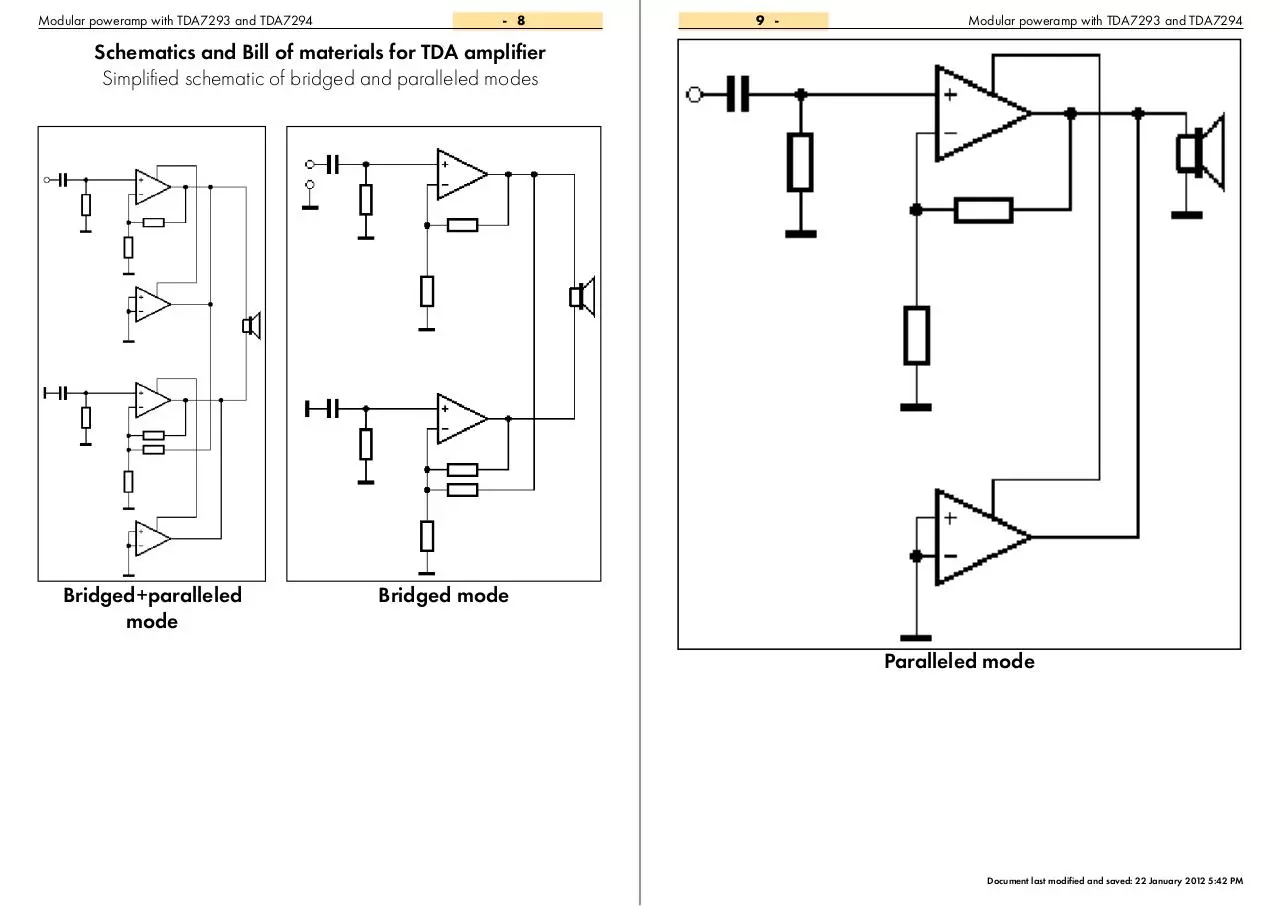
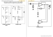
Simplified schematic of bridged and paralleled modes
Bridged+paralleled
mode
Bridged mode
Paralleled mode
Document last modified and saved: 22 January 2012 5:42 PM
�
Modular poweramp with TDA7293 and TDA7294 - 10
11 -
Modular poweramp with TDA7293 and TDA7294
Schematics and Bill of materials for TDA amplifier
Connections between single, bridge and parallel modes
1
2
3
4
5
1
6
2
3
4
5
6
R11 56k
Buff. Drv.
8
TDA7293
Title
C8
1000u 60V
GND
C
C
Number
Date:
File:
Revision
1/22/2012
D:\!Works\..\TDA7293.SchDoc
4
D
D
6
A
B
C
13
7
+V Power
+V Sig
Mute
Slave GND
22k
GND
9
10
4
1
Clip Det.
STB-GND
Bootstrap
Buff. Drv.
GND
B.L.
B.S.
B
GND
Bootst. Loader
Out
R7
5
C6
6
14
22k
22u
12
TDA7293
B.L. B.S.
C7
C8
1000u 60V
22u
C
C9
220n
GND
R2
Out -
56k
Title
TDA 7293/7294 Stage 2 (bridge module)
Size
Number
Revision
D
A4
Date:
File:
1/22/2012
Sheet of
D:\!Works\..\TDA7293-BR-MOD.SchDocDrawn By:
1
2
3
4
5
6
1
2
3
4
5
6
1
Conn3
15
14
13
12
11
10
9
8
7
6
5
4
3
2
1
+V
C1
AC 24V
R9
9.2k
+24V
Conn5
C1
330u
GND
D3
1N4148
3
GND
C4
3
GND
3
4
7
5
1
6
2
8
1
2
3
4
5
6
7
8
U1
1
2
3
4
5
6
7
8
5
1
D1
2
2 input connector
GND
Revision
1N4148
Conn2
GND
5
UPC1237
2 input connector
R1
R2
10
22k
Rel1
C
D
15
14
13
12
11
10
9
8
7
6
5
4
3
2
1
U1
13
-V
2
3
1
11
Out +/-
B.L.
B.S.
- IN
GND
1000u 60V
GND
STBY
Mute
Slave GND
9
10
4
B
+ IN
B.S.
Clip Det.
STB-GND
Buff. Drv.
Bootstrap
Bootst. Loader
Out
5
6
B.L.
12
C7
22u
14
TDA7293
C8
C
1000u 60V
C9
R6
220n
56k
GND
Title
GND
http://custompcb.blogspot.com/
http://diyguitarpa.blogspot.com/
6
6
1
A
220n
C2
Conn2
4
Conn1
D2
1N4148
C3
22n
GND
56k R7
R8
6.8k
2
B.L.
B.S.
GND
3 input connector
C2
33u
GND
GND
Number
4
12/12/2011
Sheet of
D:\!Works\..\Amp-Protection.SchDoc Drawn By:
Dual Speker protection module
4.7u
GND
Title
A4
Size
3
Date:
File:
2
15x1 pin connector
2
2
1
1
B
15
14
13
12
11
10
9
8
7
6
5
4
3
2
1
+V Power
In2
GND
Conn1
-V Power
Conn4
GND
http://custompcb.blogspot.com/
http://diyguitarpa.blogspot.com/
15
14
13
12
11
10
9
8
7
6
5
4
3
2
1
A
15
D
15x1 pin connector
15
14
13
12
11
10
9
8
7
6
5
4
3
2
1
STBY
+ IN
11
http://custompcb.blogspot.com/
http://diyguitarpa.blogspot.com/
Sheet of
Drawn By:
5
GND
1000u 60V
GND
R6
GND
A4
3
15x1 pin connector
1
Input connectors for another
modules:
• Conn4 on Main module
• Conn5 on Bridge module
• Conn2 on parallel module
22u
TDA 7293/7294 Stage 1 (main module)
Size
http://custompcb.blogspot.com/
http://diyguitarpa.blogspot.com/
Blue lines: connections between main
module and bridge module, one connection required between parallel module and bridged module.
Green lines: connection between main
module and parallel module, and between bridge module and parallel module.
Yellow lines: Connection between all
modules and speaker protection.
Red lines: Input for all channels, the dotted line is for second channel if the full
configuration is stereo.
3
3
10u
Conn5
GND
D
2
C7
2
220n
220 R10
22k
1
1
Out -
C5
- IN
7
BC212
B.L. B.S.
C9
R5
Notes
Out
2
GND
Conn6
Out +
14
B
GND
+V Sig
GND
B
GND
22u
12
Bootst. Loader
GND
22k
C6
6
Bootstrap
82k R9
T1
1
R7
5
Clip Det.
6.8k
2
10u
15x1 pin connector
2 input connector
Conn7
10u
U1
-V Power
Buff. Drv.
GND
C4
GND
GND
R8
C
C3
4
22u
-V
-V Sig
1
Mute
Slave GND
STB-GND
11
GND
Mute
10
+ IN
1
In 1
2
STBY
C3
8
GND
3
22k
22k
9
STBY
R6
C5
Conn5
GND
R4
10k
A
220n
C2
15
3
10u
In 2
R3
30k
680
-V Sig
- IN
R2
R1
15
14
13
12
11
10
9
8
7
6
5
4
3
2
1
8
2
1000u 60V
C1
Conn4
15x1 pin connector
+V Sig
GND
+V
A
1N4148
13
U1
22u
+V Power
C10
A
15x1 pin connector
GND
-V
GND
D1
220n
C2
680
-V Power
Out -
1
R1
-V Sig
+V
-V
Mute
STBY
Br. I/O
+V
2
15
15
14
13
12
11
10
9
8
7
6
5
4
3
2
1
B.L.
B.S.
3 input connector
15
14
13
12
11
10
9
8
7
6
5
4
3
2
1
3
7
Conn4
C1
3 input connector
3 input connector
Conn2
15x1 pin connector
B
Conn1
15x1 pin connector
A
2
Size
TDA 7293/7294 Stage 3 (paralel module)
Number
Revision
D
A4
Date:
File:
3
1/22/2012
Sheet of
D:\!Works\..\TDA7293-PAR-MOD.SchDoc
Drawn
By:
Document last modified and
saved:
4
5
22 January 2012 5:42 PM
6
�
Modular poweramp with TDA7293 and TDA7294 - 12
13 -
Modular poweramp with TDA7293 and TDA7294
Schematics and Bill of materials for TDA amplifier
Variations between main, bridge, and parallel modules
One channel (mono) applications:
Two channel (stereo) applications:
• About 75-80W:
1. Main module only
2. Main module and speaker protection
• About 2x75-80W:
1. Main module, speaker protection, main
module
• About 150-200W on 8 Ohm:
1. Main module and Bridge module
2. Main module, Bridge module and speaker
protection
• About 2x150-200W on 8 Ohm:
1. Main module and Bridge module, speaker
protection, main module, bridge module
• About 120W on 4 Ohm:
1. Main module, parallel module
2. Main module, parallel module and speaker
protection
• About 180W on 4 Ohm:
1. Main module, and 2 parallel module
2. Main module, 2 parallel module, and
speaker protection
• About 220W on 8 Ohm:
1. Main module, 1 parallel module, bridge
module and 1 parallel module
2. Main module, 1 parallel module, bridge
module, 1 parallel module and speaker
protection
• About 300W on 4 Ohm:
1. Main module, 2 parallel module, bridge
module and 2 parallel module
2. Main module, 2 parallel module, bridge
module, 2 parallel module and speaker
protection
• About 2x120W on 4 Ohm:
1. Main module, parallel module, speaker
protection, main module, parallel module
• About 2x180W on 4 Ohm:
1. Main module, and 2 parallel module,
speaker protection, main module, 2 parallel
module
• About 2x220W on 8 Ohm:
1. Main module, 1 parallel module, bridge
module and 1 parallel module, speker
protection, main module, 1 parallel module,
bridge module and 1 parallel module
PCB for modular expandable
TDA amplifier project
• About 2x300W on 4 Ohm:
1. Main module, 2 parallel module, bridge
module and 2 parallel module, speaker
protection, main module, 2 parallel module,
bridge module and 2 parallel module
Bridge application:
Single application:
1) - 1 TDA729x IC paralleled / bridge
1) - 1 TDA729x IC paralleled
2) - 2 TDA729x IC paralleled / bridge
2) - 2 TDA729x IC paralleled
Document last modified and saved: 22 January 2012 5:42 PM
�
Modular poweramp with TDA7293 and TDA7294 - 14
15 -
PCB for TDA729x amplifier project
PCB of main module
TOP LAYER
Conn1
C6
Conn5
This module can be used
alone for mono - or with
speaker protection - for stereo amplifiers. This is the
first module for all possible
configurations. Conn4 can
be connected to the right
side of speaker protection
only, Conn2 is the input of
bridge, parallel or speaker
protection modules.
Conn4
BOTTOM LAYER
U1
Conn5
R6
R7
C6
C5
R1
C3
C9
C1
C2
C8
Conn6
C3
C4
C9
C8
R1
C10
C2
R8R9 T1 Conn7
1
3
C1
R6 D1 R2 R3 R4 R7 R10R5 R11
TOP LAYER
R2
OVERLAY ON TOP LAYER
U1
Conn2
Notes
C5
PCB for TDA729x amplifier project
PCB of bridge module
BOTTOM LAYER
OVERLAY ON TOP LAYER
Modular poweramp with TDA7293 and TDA7294
Notes
This is the bridge module of this project. This
module can be connected to the right side
of first (main) module
only. This module duplicate the output power with 8 ohm speakers. 4 Ohm speakers
cannot be used with
bridge amplifier if parallel modules not used.
Document last modified and saved: 22 January 2012 5:42 PM
�
Modular poweramp with TDA7293 and TDA7294 - 16
17 -
PCB for TDA729x amplifier project
PCB of parallel module
TOP LAYER
Modular poweramp with TDA7293 and TDA7294
PCB for TDA729x amplifier project
PCB of speaker protection module
TOP LAYER
BOTTOM LAYER
BOTTOM LAYER
Notes
U1
Conn1
C1
C2
This is the parallel module of this amplifier project. This mode can be
connected to the right
side of first (main) module to use with 4 ohm
speakers, or can be
connected to the second (bridge) module to
use bridged amp with 4
ohm speakers instead of
8. For parallel amplification use only TDA7293
only. This module can
be duplicated on single or bridged configurations after main
or bridged module
to increase the maximum output current. It’s
mean, this module can
be connected to the
previous parallel module as second parallel
output.
R7
C3
R8
R9R2
U1
C2
C1
Conn4
D3
C4
D1
Rel1
D2
R1
Conn5
Conn1
Conn2
OVERLAY ON TOP LAYER
R6
C9
Conn2
OVERLAY ON TOP LAYER
C8
Notes
This is very simple, cheap and optional module for all configuration of this amplifier project with
UPC1237. This module possible to use for all one channel mono and all two channels stereo configurations. This module (if used) must be connected between the last module of left channel and the first
(main) module of right channel. Otherworld, the left side connector (Conn3) of speaker protection
must be connected to the last module (main, bridge or parallel) of left channel, and the right side connector (Conn4) must be connected to the (first) main module of right channel.
Document last modified and saved: 22 January 2012 5:42 PM
�
 Historical archive . public document